The EXTERNAL MODULE CTRL dialog box controls the configuration of attached broadband modules and systems.
For Modular Broadband (Modular BB), an MS4647B VNA with Option 8x is required with a connected 3739C Broadband/mmWave Test Set and MA25x00A or 3743x mmWave Modules.
For Standard BB, an MS464xB Series VNA is required with a connected 3738A Broadband/mmWave Test Set and related modules and signal generators.
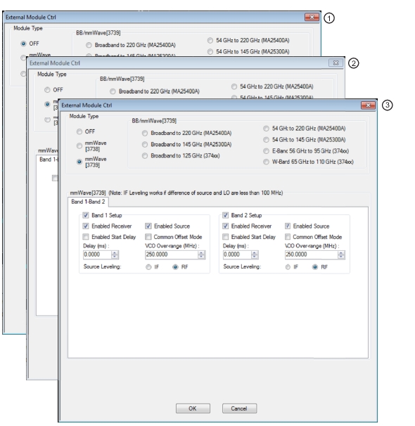
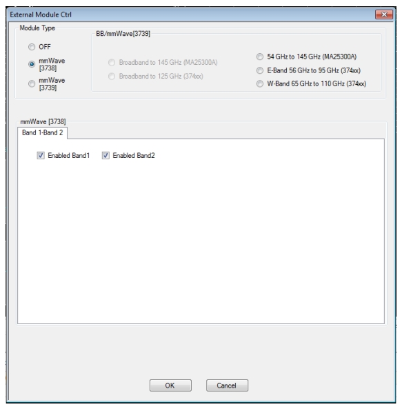
2. Dialog box with Module Type mmWave (3738) selected. Selection boxes enable Band 1 and/or Band 2.
3. Dialog box with Module Type mmWave (3739) selected. Selection boxes and control fields enable configuration control of Band 1 and/or Band 2.
EXTERNAL MODULE CTRL Dialog Box – Broadband
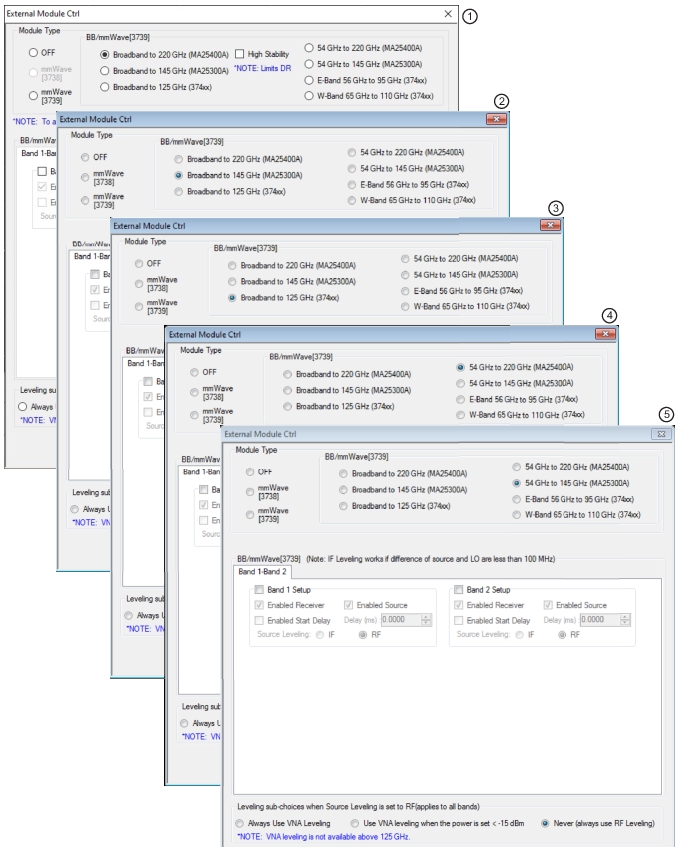
1. Dialog box with Module Type Broadband to 220 GHz selected. Selection boxes and control fields enable configuration control of Band 1 and/or Band 2. This module type and mode only available with MS4647B VNAs equipped with Option 8x.
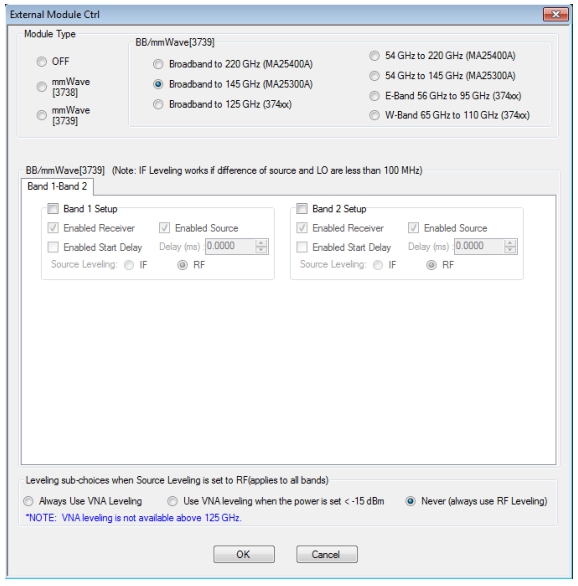
2. Dialog box with Module Type Broadband to 145 GHz selected. Selection boxes and control fields enable configuration control of Band 1 and/or Band 2. This module type and mode only available with MS4647B VNAs equipped with Option 8x.
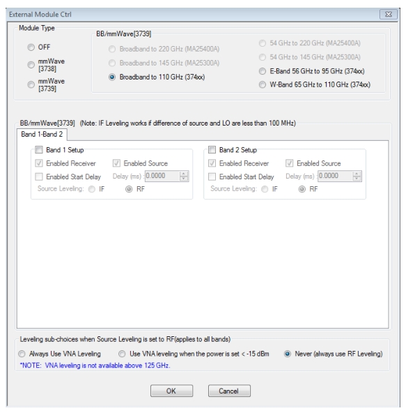
3. Dialog box with Module Type Broadband to 125 GHz selected. Selection boxes and control fields enable configuration control of Band 1 and/or Band 2. This module type and mode only available with MS4647B VNAs equipped with Option 8x.
4. Dialog box with Module Type 54 GHz to 220 GHz selected. Selection boxes and control fields enable configuration control of Band 1 and/or Band 2. This module type and mode only available with MS4647B VNAs equipped with Option 8x.
5. Dialog box with Module Type 54 GHZ to 220 GHz selected. Selection boxes and control fields enable configuration control of Band 1 and/or Band 2. This module type and mode only available with MS4647B VNAs equipped with Option 8x.
EXTERNAL MODULE CTRL Dialog Box – E-Band, and W-Band
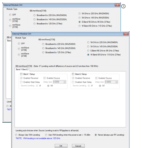
1. Dialog box with Module Type E-Band 56 GHz to 95 GHz selected. Selection boxes and control fields enable configuration control of Band 1 and/or Band 2. This module type and mode only available with MS4644B, MS4645B, or MS4647B VNAs equipped with Options 08x.
2. Dialog box with Module Type W-Band 65 GHz to 110 GHz selected. Selection boxes and control fields enable configuration control of Band 1 and/or Band 2. This module type and mode only available with MS4644B, MS4645B, or MS4647B VNAs equipped with Option 8x.
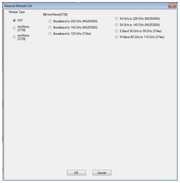
EXTERNAL MODULE CTRL Dialog Box – Module Type = OFF
External mmWave or broadband test sets are not being used. The dialog in this state is shown in Figure: EXTERNAL MODULE CTRL Dialog Box – Set for OFF below. The 3739 test set does not require external synthesizers so these non-OFF choices will always be available assuming Option 8x is present. The 3738 test set does not require additional options but does require the presence of external synthesizers 1 and 2 on the GPIB bus.
The 3738X Test set is being used with conventional OEM mmWave modules (the ME7828 family of systems). In this case, a check box will be available per-defined band to allow activation of the test set in that band. This option is only available if External Sources 1 and 2 are connected and active. There are no other parameters to select other than to activate or de-activate on a band-by-band basis.
EXTERNAL MODULE CTRL Dialog Box – Set for mmWave (3738)
As an example to show how this selection might be used, consider a DUT that is a downconverter taking 250 to 300 GHz down to a fixed IF of 1 GHz. The LO is sub-harmonically driven with an effective multiplier of 18 and will be driven from External Source 3 (EXT. SRC 3). The RF is supplied by an external mmWave module (WR-03 waveguide in this case) which also has an effective source multiplier of 18 and this will be driven from EXT. SRC. 1. This external module also has an LO input (x20 effective multiplier) that will be driven from EXT SRC 2. It is desired to measure both return loss (at the RF) of the DUT as well as its conversion loss. This will require two different multiple source setups since the conversion paths in the VNA are different. The example measurement is described below:
Return Loss Measurement
Connect all external synthesizers and make sure the GPIB addresses match and 10 MHz clocks are synchronized (or higher frequency references if those are being used). It is desired that the DUT LO port be driven since that can affect return loss. Since the IF outputs of the mmWave module will be used (and routed to the VNA rear panel), the Ext Module Ctrl for BB/mmWave must be enabled.
• Band 1: 250-300 GHz
• Int Src (Internal Source) = 1/1(CW 3 GHz)
• We are not using the internal source so it is just parked.
• Ext Src1 (External Source) = 1/18(f +0)
• Ext Src2 = 1/20(f+12.35 MHz)
• The system IF (rear panel) is 12.35 MHz.
• Ext Src3 = 1/18(f+ 1 GHz)
• Rcvr (Receiver) = 1/1(CW 2 GHz)
• We are not using the internal LO so this is just parked.
Conversion Loss Measurement
In this case, Ext Module Ctrl must be OFF since we will not be using the rear panel IFs. Note that this also disables the test set, so some care is required with RF signal cabling.
• Band 1: 250 to 300 GHz
• Int Src = 1/1(CW 3 GHz)
• We are not using the internal source so it is just parked.
• Ext Src1 = 1/18(f +0)
• Ext Src2 = 1/1 (CW 2 GHz)
• The external mmWave module LO is not being used.
• Ext Src3 = 1/18(f+ 1 GHz)
• Rcvr = 1/1(CW 1 GHz)
• The DUT IF is routed to a port or receiver loop so it can be converted.
The mmWave (3739) selection also assumes the use of OEM mmWave modules but with the 3739 Test Set. Details on some applicable modules, from a hardware perspective, are discussed below and in Multiple Source. Any multiplied transceivers can be used here as long as the frequency and power plans are consistent with the VectorStar system with the 3739X test set. The Test Set offers additional power control options and assumes the use of the internal VNA sources so there are some additional selection options as suggested by Figure: EXTERNAL MODULE CTRL Dialog Box – Set for mmWave (3739) below.
EXTERNAL MODULE CTRL Dialog Box – Set for mmWave (3739)
The external module control dialog is shown as configured for a single active band of mmWave (3739).
The selection choices per band are described below:
• Enabled Receiver
Use the receiver in the remote modules. Above this breakpoint, the VNA system LO will be set appropriately in terms of frequency and power, the test set configured, and the VNA rear panel IFs will be activated.
• Enabled Source
Use the source multipliers in the remote modules. When enabled the VNA synthesizers will be set appropriately, the test set configured as needed, and ALC leveling prepared (see below).
• Enabled Start Delay
This enables a fixed delay at the beginning of the band. This could be useful for certain slow settling DUT measurements or for very low power levels.
• Common Offset mode
At higher multiples (generally for modules running over 300 GHz), it may be desired to improve source correlation to reduce trace noise. This can be done with the Common Offset mode bit (and it automatically done in the 3739 mmWave modes discussed in chapter 16). If the source and receiver frequencies (when reduced to the 2.5-5 GHz range by division) differ by more than about 50 MHz with this bit selected, phase lock errors may occur so this selection is not appropriate for millimeter wave mixer measurements but is useful for IMD and other related measurements.
• VCO Overrange
Normally, the internal VNA multipliers switch at 5, 10, 20, and 40 GHz. In some mmWave modules operating with high multipliers, it may be desirable to push those switch points out further (up to 5.5, 11,22, and 44 GHz typical but not guaranteed). This overrange (expressed in MHz relative to the 5 GHz breakpoint) sets the new breakpoints.
• Source Leveling
The leveling choice determines which detection path is used (RF implies the VNA detection on the RF drive path, IF uses the test set detection on a reference IFs). Additional cals using the mmWave ALC subsystem may be required. Generally IF leveling is only valid if the IF coming from the mmWave modules is under 100 MHz.
This right side of the radio button array is for the broadband operation (with the 3739x test set and the MA25300A, MA25400A, and 3743x modules) and for banded operation (using the 3739x test set and the 3743x or 3744x modules). The selection for BB/mmWave is straightforward. When checked in a given band, the test set will be activated, the VNA internal transfer switch will be shut down, and the rear panel IF ports on the VNA will be activated.
There are seven choices for use with the MA25300A, MA25400A, 3743X, and 3744X modular heads:
• Broadband to 220 GHz (MA25400A)
• High Stability: Provides increased stability in the face of temperature changes. Dynamic range will be reduced. Toggles the High Stability mode on and off.
• 54 GHz to 220 GHz (MA25400A)
• Broadband to 145 GHz (MA25300A)
• 54 GHz to 145 GHz (MA25300A)
• Broadband to 125 GHz (374xx)
• E-Band (374xx)
• W-Band (374xx)
The distinction between these selections is based on the imposed frequency range limits when activated.
• Broadband to 220 GHz allows from the lower instrument limit up to 220 GHz (using MA25400A modules).
• 54 GHz to 220 GHz allows from 54 GHz to 220 GHz. (using MA25400A modules)
• Broadband to 145 GHz allows from the lower instrument limit up to 145 GHz (using MA25300A modules).
• 54 GHz to 145 GHz allows from 54 GHz to 145 GHz. (using MA25300A modules)
• Broadband to 125 GHz allows from the lower instrument limit up to 125 GHz (using (374xx modules).
• E-Band allows 56-95 GHz (under range to 54.000000001 GHz allowed).
The MA25300A, MA25400A, 3743x and 3744x modules have independent source and receiver paths that can be selected from the dialog. The selections can be interpreted as follows:
Enabled Receiver
Use the receiver in the remote modules above the receiver breakpoint (30 GHz). Above this breakpoint, the VNA system LO will be set appropriately in terms of frequency and power, the test set configured, and the VNA rear panel IFs will be activated.
Enabled Source
Use the source multipliers in the remote modules above the source breakpoints (54 GHz). Above the first breakpoint, the VNA synthesizers will be set appropriately, the test set configured as needed, and ALC leveling prepared (see below). Note that the above and below 54 GHz power control setting apply when this source feature is enabled (more details earlier in this chapter).
Enabled Start Delay
This enables a fixed delay at the beginning of the band. This could be useful for certain slow settling DUT measurements or for very low power levels.
Source Leveling
The default operation of the 3739-based modes (when not in multiple source) is to use IF leveling in order to get wide power ranges but if the source and receiver frequencies are not close enough (or the receiver is not enabled), then an IF is not available for leveling. The leveling defaults to RF in multiple source 3739-based modes with broadband/mmWave and this is recommended unless one knows the IF will be available (up to about 100 MHz) in the module for leveling. Separate ALC calibrations are available for RF and IF leveling and the system will automatically index the correct calibration table.
EXTERNAL MODULE CTRL Dialog Box – Set for Broadband to 145 GHz
The external module control set for broadband/mmWave (3739X-based) mode is shown with 2 bands configured.
This right side of the radio button array is for the broadband operation (with the 3739X test set and 3743X modules), and for banded operation (using the 3739X test set and the 3743X or 3744X modules). The selection for BB/mmWave is straightforward. When checked in a given band, the test set will be activated, the VNA internal transfer switch will be shut down, and the rear panel IF ports on the VNA will be activated.
There are three choices for use with the 3743X and 3744X modular heads:
• Broadband to 110 GHz
• E-Band
• W-Band
The distinction between these selections is based on the imposed frequency range limits when activated.
• Broadband allows from the lower instrument limit up to 110 GHz.
• E-Band allows 56 GHz to 95 GHz (under range to 54.000000001 GHz allowed).
• W-Band allows 65GHz to 110 GHz.
EXTERNAL MODULE CTRL Dialog Box with Broadband to 110 GHz selected (1 of 2)
The external module control set for broadband (3739X-based) mode is shown here with available selections. This dialog box appears when the MS464xB has Options 086, 087, 088, or 089.
These 3743x and 3744x modules have independent source and receiver paths that can be selected from the above dialog. The selections can be interpreted as follows:
Enabled Receiver
Use the receiver in the remote modules above the receiver breakpoint (30 GHz). Above this breakpoint, the VNA system LO will be set appropriately in terms of frequency and power, the test set configured, and the VNA rear panel IFs will be activated.
Enabled Source
Use the source multipliers in the remote modules above the source breakpoints (54 GHz). Above the first breakpoint, the VNA synthesizers will be set appropriately, the test set configured as needed, and ALC leveling prepared (see below). Note that the above and below 54 GHz power control setting apply when this source feature is enabled (more details in Chapter 16).
Enabled Start Delay
This enables a fixed delay at the beginning of the band. This could be useful for certain slow settling DUT measurements or for very low power levels.
Source Leveling
The default operation of the 3739-based modes (when not in multiple source) is to use IF leveling in order to get wide power ranges but if the source and receiver frequencies are not close enough (or the receiver is not enabled), then an IF is not available for leveling. The leveling defaults to RF in multiple source 3739-based modes with broadband/mmWave and this is recommended unless one knows the IF will be available (up to about 100 MHz) in the module for leveling. Separate ALC calibrations are available for RF and IF leveling and the system will automatically index the correct calibration table.
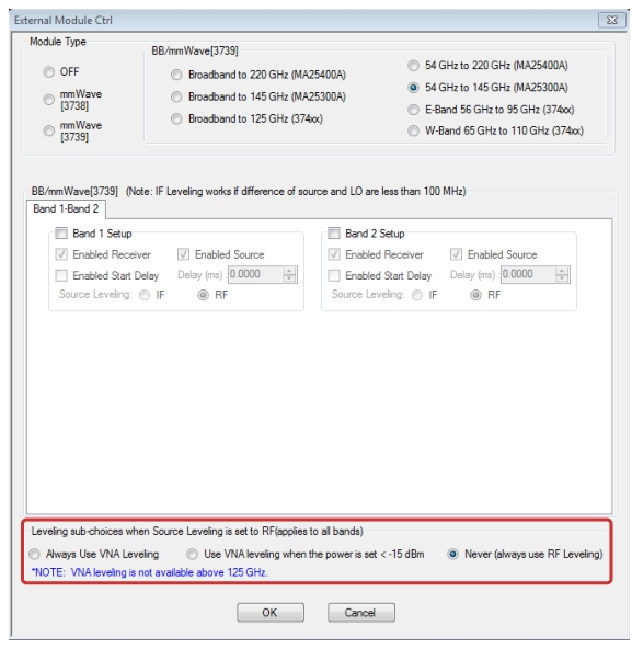
EXTERNAL MODULE CTRL Dialog Box – with Low Power Leveling and RF/VNA Leveling
When any of the five choices under BB/mmWave [3739] are selected and there is a valid VNA leveling cal in effect, the selections for VNA leveling the sub-choices (highlighted below) will be visible. For all other cases, it will not be visible. Note that the leveling sub choices is per-channel but the source leveling is per-band. See Figure: EXTERNAL MODULE CTRL Dialog Box – Set for Broadband to 145 GHz below.
The choices for use with the MA25x00A, 3743X and 3744X modular heads are:
• Broadband to 220 GHz (MA25400A)
• 54 GHz to 220 GHz (MA25400A)
• Broadband to 145 GHz (MA25300A)
• 54 GHz to 145 GHz (MA25300A)
• Broadband to 125 GHz (374xx)
• E-Band (374xx)
• W-Band (374xx).
EXTERNAL MODULE CTRL Dialog Box – Low Power Leveling and RF/VNA Leveling Enabled
The MA25300A, MA25400A, 3743x and 3744x modules have independent source and receiver paths that can be selected from the above dialog. The selections are defined as follows:
Enabled Receiver
Use the receiver in the remote modules above the receiver breakpoint (30 GHz). Above this breakpoint, the VNA system LO will be set appropriately in terms of frequency and power, the test set configured, and the VNA rear panel IFs will be activated.
Enabled Source
Use the source multipliers in the remote modules above the source breakpoints (54 GHz). Above the first breakpoint, the VNA synthesizers will be set appropriately, the test set configured as needed, and ALC leveling prepared (see below). Note that the above and below 54 GHz power control setting apply when this source feature is enabled (more details earlier in this chapter).
Enabled Start Delay
This enables a fixed delay at the beginning of the band. This could be useful for certain slow settling DUT measurements or for very low power levels.
Source Leveling
The default operation of the 3739-based modes (when not in multiple source) is to use IF leveling in order to get wide power ranges but if the source and receiver frequencies are not close enough (or the receiver is not enabled), then an IF is not available for leveling. The leveling defaults to RF in multiple source 3739-based modes with broadband/mmWave and this is recommended unless one knows the IF will be available (up to about 100 MHz) in the module for leveling. Separate ALC calibrations are available for RF and IF leveling and the system will automatically index the correct calibration table.
Leveling Sub-choices
This feature allows the user to select three different leveling sub-choices when the Source Leveling type selected is RF.
Note
VNA leveling is not available above 125 GHz.
• Always Use VNA Leveling
• Uses the leveling detector in the base VNA (which is better for control range but less so for stability).
• Use VNA leveling when the power is set < –15 dBm
• Uses VNA leveling for requested power levels < –15 dBm and RF leveling otherwise.
• Never (always use RF Leveling)
• Uses the level detector inside the BB module (best for stability but not for control range)