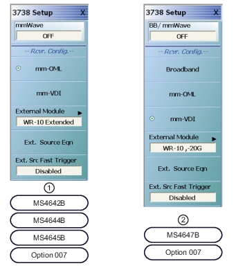
1. 3738 SETUP menu for MS4642B, 44B, and 45B VNAs equipped with Receiver Offset Option 007.
2. 3738 SETUP menu for MS4647B VNA equipped with Option 007.
Receiver Configuration Button Group Start
Depending on the instrument model and equipped options, the receiver configuration button group allows only one type to be selected.
mmWave
Shown on MS4642B, 44B, or 45B VNAs with Option 7. Select toggles the broadband capability on and off. The broadband state is shown in the button field.
BB/mmWave
Shown on the MS4647B VNA with Option 7. Select toggles the broadband/mmWave capability on and off. The state is shown in the button field.
Broadband
Select sets the receiver configuration as Broadband.
mm-OML
Select sets the receiver configuration as mm-OML using OML brand mmWave modules.
mm-VDI
Select sets the receiver configuration as mm-VDI using VDI brand mmWave modules.
Receiver Configuration Button Group End
The mm-VDI button is the last button in the receiver configuration button group.
External Module
Select displays the EXTERNAL MODULE SELECTION dialog box.
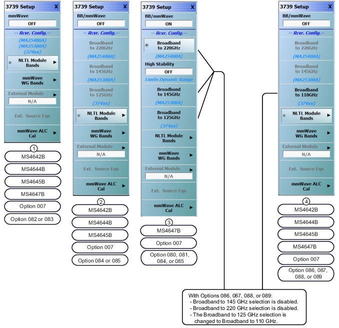
1. The 3739 SETUP Menu for MS4642B, 44B, 45B, and 47B VNAs with Option 7 and Option 082 or 083.
2. The 3739 SETUP Menu for MS4642B, 44B, and 45B VNAs with Option 7 and Option 084 or 085.
3. The 3739 SETUP Menu for MS4647B VNAs with Option 7 and a Option 80, 081, 084, or 085.
4. The 3739 SETUP Menu for MS4642B, 44B, 45B, and 47B VNAs with Options 086, 087, 088, or 089. The 145 GHz and 220GHz selections are disabled and the 125 GHz selection is changed to 110 GHz.
mmWave
Part of the Receiver Configuration button selection group. Only on MS4642B, MS4644B, and MS4645B VNAs equipped with Option 8x. Toggles the mmWave capabilities on and off.
BB/mmWave
Part of the Receiver Configuration button selection group. Only on MS4647B VNAs equipped with Option 08x. Toggles the broadband/mmWave capabilities on and off.
Broadband to 220 GHz
Part of the Receiver Configuration button selection group. Only on MS4647B VNAs equipped with Option 08x. If this is selected, the External Module and Ext. Source Eqn buttons below are not available.
High Stability
Provides increased stability in the face of temperature changes. Dynamic range will be reduced. Toggles the High Stability mode on and off. This button is only available if a 220 GHz band with the MA25400A module is selected.
Broadband to 145 GHz
Part of the Receiver Configuration button selection group. Only on MS4647B VNAs equipped with Option 08x. If this is selected, the External Module and Ext. Source Eqn buttons below are not available.
Broadband to 125 GHz
Part of the Receiver Configuration button selection group. Only on MS4647B VNAs equipped with Option 08x. If this is selected, the External Module and Ext. Source Eqn buttons below are not available.
Broadband to 110 GHz
Part of the Receiver Configuration button selection group. Only on MS4647B VNAs equipped with Options 086, 087, 088, or 089. If this is selected, the External Module and Ext. Source Eqn buttons below are not available.
NLTL Module Bands
Select displays the NLTL MODULE dialog box, which allows one of the banded NLTL sweep bands to be chosen.
Only on MS464xB VNAs equipped with Option 08x.
If this item is selected, the External Module and Ext. Source Eqn buttons (below) are not available.
Select displays the EXTERNAL MODULE SELECTION dialog box, where separate control tabs allow configuration of either OML or VDI mmWave modules. Once a module has been selected, the module name appears in the button field.
1. The NLTL MODULE menu for MS4642B, 44B, and 45B VNAs with Option 7 and Option 082, 083, 084, or 085. The NLTL MODULE menu for MS4647B VNAs with Option 7 and Option 080, 081, 082, 083, 084, or 085.
2. The NLTL MODULE menu for MS4642B, 44B, 45B, or 47B VNAs with Option 7 and Option 086, 087, 088, or 089.
54 GHz to 220 GHz
Part of the Receiver Configuration button selection group. Only on MS464xB VNAs equipped with Option 08x. If this is selected, the External Module and Ext. Source Eqn buttons on the 3739 Menu are not available.
54 GHz to 145 GHz
Part of the Receiver Configuration button selection group. Only on MS464xB VNAs equipped with Option 08x. If this is selected, the External Module and Ext. Source Eqn buttons on the 3739 Menu are not available.
E-Band 56 GHz to 95 GHz
Part of the Receiver Configuration button selection group. Only on MS464xB Series VNAs equipped with Option 8x. If this is selected, the External Module and Ext. Source Eqn buttons on the 3739 Menu are not available.
W-Band 65 GHz to 110 GHz
Part of the Receiver Configuration button selection group. Only on MS464xB Series VNAs equipped with Option 8x. If this is selected, the External Module and Ext. Source Eqn buttons on the 3739 Menu are not available.
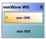
• MAIN | Application | APPLICATION | Rcvr Config | RCVR CONFIG | mmWave (3739 Setup) | 3739 SETUP | mmWave WG Bands | mmWAVE WG Menu
• MAIN | Application | APPLICATION | Rcvr Config | RCVR CONFIG | BB/mm Wave (3739 Setup | 3739 SETUP | mmWave WG Bands | mmWAVE WG Menu
mmWAVE WG Menu
IF
mm-OML
Only on MS464xB Series VNAs equipped with Option 8x. Select enables the External Module and the Ext. Source Eqn buttons on the 3739 Menu. The External Module button links to a module selection dialog and configures the VNA to use OML mmWave modules. The module selection is done using the External Module button described below to access the EXTERNAL MODULE SELECTION dialog box. The Ext. Source Eqn (External Source Equation) button links to the MODIFY EXTERNAL SOURCE EQUATIONS dialog box.
mm-VDI
Only on MS464xB Series VNAs equipped with Option 8x. Select enables the External Module button which links to a module selection dialog and configures the VNA to use VDI mmWave modules. The module selection is done using the External Module button below to access the EXTERNAL MODULE SELECTION dialog box.
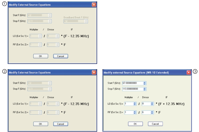
MODIFY EXTERNAL SOURCE EQUATIONS Dialog Box
Previous
• The previous menu varies depending on the instrument model.
• There are multiple navigation paths to this menu.
• MAIN | Application | APPLICATION | Rcvr Config | RCVR CONFIG | BB/mmWave (3739 Setup) | 3739 SETUP | mmWave ALC Cal | mmWAVE ALC CAL
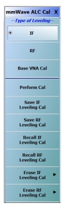
mmWAVE ALC CAL Menu – mmWave Automatic Level Control Calibration
Type of Leveling Button Group Start
The IF, RF, and Base VNA Cal buttons at the top of the menu form a button selection group where only one type of leveling can be selected.
IF
If the IF type of leveling is selected, it provides the advantages of RF leveling described below plus the benefit of greater power control range and a lower minimum leveled power (at least 20 dB lower typically). As one approaches a 100 MHz difference between source and receiver frequencies, the power control range will start to decrease as will power control accuracy. The use of IF leveling is not recommended for source-receiver frequency differences greater than 100 MHz.
RF
If the RF type of leveling is selected, it provides a leveled RF output power with improved source match, protection against over powering the DUT, and insuring that the DUT is operating in its designated power range.
Base VNA Cal
If the VNA type of leveling is selected, it turns the RF or IF ALC off and the ALC accuracy is set as that for the standalone VNA instrument.
Type of Leveling Button Group End
The Base VNA Cal button is the end of the Type of Leveling button group.
Perform Cal
Select starts the calibration type selected above (IF, RF, or VNA) and displays the mmWAVE ALC CAL dialog box. A suffix is added to the dialog name denoting the selected mmWave module.
• 3739 Setup | BB/mmWave option should be set to ON
• Either mm-OML or mm-VDL should be selected
Navigation
• There are multiple navigation paths to this menu.
• MAIN | Application | APPLICATION | Rcvr Config | RCVR CONFIG | BB/mmWave (3739 Setup) | 3739 SETUP | mmWave ALC Cal | mmWAVE ALC CAL | Perform Cal | mmWAVE ALC CAL dialog box
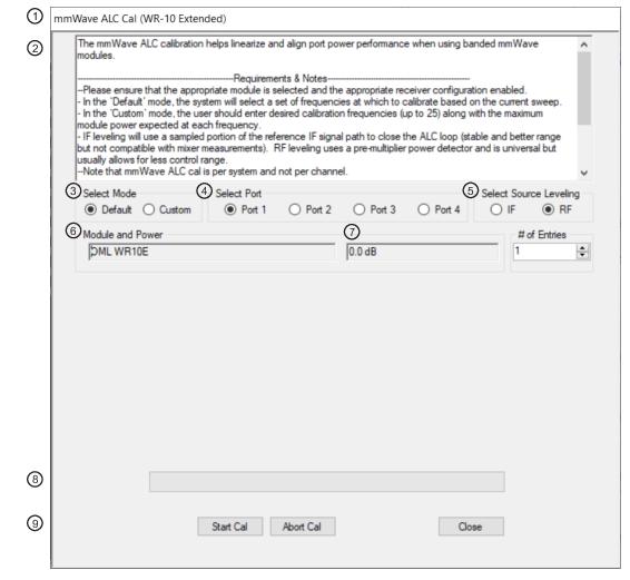
mmWAVE ALC CAL (MODULE NAME) Dialog Box (Default Mode) (1 of 2)
1. mmWAVE ALC CAL (MODULE NAME) Dialog Box
2. General instructions. See below.
3. Select Mode Radio Buttons.
4. Select Port Radio Buttons – Select either Port 1 or Port 2.
5. Select Source Leveling as either IF or RF.
6. Connected Module Name Display.
7. Power (dB) Level Display.
8. Calibration Progress Bar
9. Dialog Box Control Buttons.
General Instructions
ALC Calibration consists of several sub calibrations that ensure accurate output power and overall system.
Requirements and Notes
The following requirements and notes apply:
• Please ensure that the appropriate module is selected and enabled.
Instructions (Default Mode)
1. Select Default Mode.
2. Select appropriate port.
3. Select Leveling as either IF or RF.
4. Select Start Cal to perform the calibration.
5. Select Abort Cal to stop the calibration.
6. Select Close to exit the dialog box to the mmWAVE ALC CAL menu.
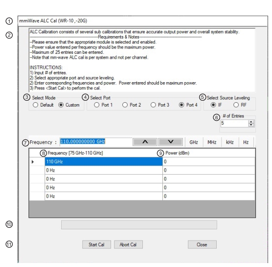
mmWAVE ALC CAL (MODULE NAME) Dialog Box (Custom Mode)
1. mmWAVE ALC CAL (MODULE NAME) Dialog Box
2. General instructions. See below.
3. Select Mode Radio Buttons.
4. Select Port Radio Buttons – Select either Port 1 or Port 2.
5. Select Source Leveling as either IF or RF.
6. # of Entries (Number of Entries) input field. Up to 25 frequency/power combinations can be entered.
7. Frequency Input. When this has the focus, the Frequency Field Toolbar appears to allow value and units input for each entry row.
8. Power (dB) level for each frequency. When it has the focus, the Power (dB) field toolbar (not shown here) appears to allow value input for each entry row.
9. Power (dB) Field Toolbar.
10. Calibration Progress Bar.
11. Dialog box control buttons.
General Instructions (Custom Mode)
ALC Calibration consists of several sub calibrations that ensure accurate output power and overall system.
Requirements and Notes
The following requirements and notes apply:
• Power value entered per frequency should be the maximum power.
• Maximum of 25 entries can be entered.
Instructions
1. Input the # of entries (Number of Entries).
2. Select appropriate port.
3. Enter corresponding frequencies and power. Power entered should be maximum power.
4. Select Start Cal to perform the calibration.
5. Select Abort Cal to stop the calibration.
6. Select Close to exit the dialog box to the mmWAVE ALC CAL menu.
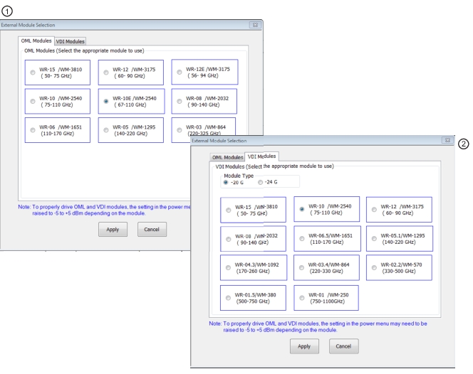
1. The OML tab is selected and the available OML Modules are shown. Select a module radio button to configure that module.
2. The VDI tab is selected and the available VDI Modules are shown. Select a module radio button to configure that module. Note that VDI modules have two basic types: -20 G and -24 G. The type indicates the maximum LO/RF frequency (in GHz) that the module requires. The module type selected here must match the module being used, as the two types have slightly different frequency plans.
External Module Summary Notes
• WR Numbers
The WR number abbreviation is for “rectangular waveguide” using English measurement units. The interior dimensions of waveguides have an aspect ration of 2:1, where the broad wall is twice the dimension of the narrow wall. The number following is approximately the broad wall length in mils (0.001 in) divided by 10. For example, the WR-62 waveguide has a broad wall dimension of 620 mils (0.620 in) divided by 10 which yields 62. The larger the WR Number, the lower the operating frequency range. Both OML Modules and VDI Modules reference WR and the equivalent WM Numbers.
• WM Numbers
WM numbers are an emerging metric specification for equivalent and new waveguides using metric measurements. The interior opening aspect ratio follows the same 2:1 ratio. The number is derived from the broadwall dimension in micrometers (µm or 0.0001 m). For example, the WM-570 has a broadwall dimension of 570 µm. The larger the WM Number, the lower the operating frequency range. Both OML Modules and VDI Modules reference both WR and the equivalent WM Numbers.
• Anritsu Numbers
Anritsu has the following Broadband/mmWave module models:
• MA25300A mmWave Module, 54 to 145 GHz – Requires a MS4647B VNA with Broadband/mmWave Option 8x and a 3739B/C Test Set.
• MA25400A mmWave Module, 54 to 220 GHz – Requires a MS4647B VNA with Broadband/mmWave Option 8x and a 3739B/C Test Set.
• 3743A mmWave Module, 54 to 125 GHz – Requires a MS4647B VNA with Broadband/mmWave Option 8x and a 3739x Test Set.
• 3743AX mmWave Module, 54 to 125 GHz – Requires a MS4647B VNA with Broadband/mmWave Option 8x and a 3739x Test Set.
• 3743E mmWave Module, 54 to 110 GHz – Requires a MS4647B VNA with Broadband/mmWave Option 8x and a 3739x Test Set.
• 3743EX mmWave Module, 54 to 110 GHz – Requires a MS4647B VNA with Broadband/mmWave Option 8x and a 3739x Test Set.
• 3744A-EW/SM6597 mmWave Module, W-Band, 65 to 110 GHz – Requires any MS464xB Series VNA equipped with mmWave Option 8x and a mmWave Test Set.
• 3744E-EW mmWave Module, W-Band, 65 to 110 GHz – Requires any MS464xB Series VNA equipped with mmWave Option 8x and a mmWave Test Set.
• 3744A-EE/SM6499 mmWave Module, E-Band,56 to 95 GHz – Requires any MS464xB Series VNA equipped with mmWave Option 8x and a mmWave Test Set.
• 3744E-EE mmWave Module, E-Band,56 to 95 GHz – Requires any MS464xB Series VNA equipped with mmWave Option 8x and a mmWave Test Set.
• 3743A-Rx; This module is typically ordered as an accessory to the ME7838 system. When ordering this module, the base VectorStar VNA must have Noise Figure Option 41
• 3743E Rx; This module is typically ordered as an accessory to the ME7838 system. When ordering this module, the base VectorStar VNA must have Noise Figure Option 41.