Mixer Setup – Multi-Channel – Frequency Sweep – Menu Set
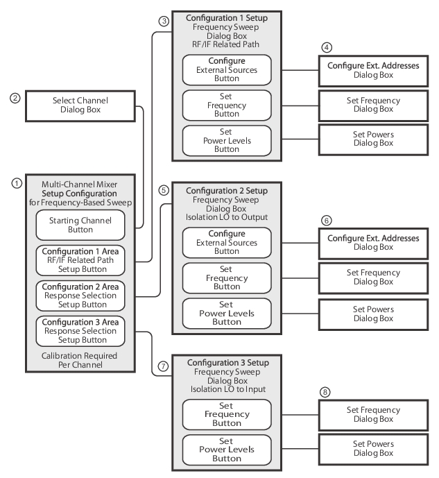
The multi-channel mixer setup provides additional measurement capability over multiple channels and consists of one central control dialog box with multiple supporting dialog boxes. The multi-channel mixer setup for frequency-based sweeps is similar to the controls for the active channel version described above. Additional parameters can be measured, requiring addition dialogs to configure the mixer. In Figure: MULTI-CHANNEL MIXER SETUP Dialog Boxes – Frequency-Based Sweep (1 of 2) below, the illustration shows the relationship between the main and supporting dialog boxes.
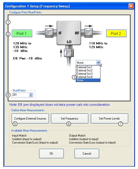
3. CONFIGURATON 1 SETUP Dialog Box for RF/IF Related Paths NOTE: When Dual Source Architecture is selected on the MIxer Wizard Configuration screen, the Configure External Sources Button is disabled.
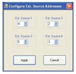
4. Configuration 1 Dialog Boxes for External Source Address, Frequency, and Power.
5. CONFIGURATON 2 SETUP Dialog Box for Isolation LO to Output NOTE: When Dual Source Architecture is selected on the MIxer Wizard Configuration screen, the Configure External Sources Button is disabled.
6. Configuration 2 Dialog Boxes for External Source Address, Frequency, and Power.
7. CONFIGURATON 3 SETUP Dialog Box for Isolation LO to Input
8. Configuration 3 Dialog Boxes for Frequency and Power.
Mixer Setup – Multi-Channel – Frequency Sweep – Available Measurements
The table below lists the available frequency-based mixer measurements. On the main dialog box, check boxes allow individual measurement selections. For each configuration area (Configuration 1, Configuration 2, and Configuration 3), the Setup button for that area displays the setup dialogs for that configuration.
Available Measurements for Frequency-Based Sweep
Measurement
Response
Display Format
Channel
Configuration 1 – RF/IF Related Path – Response selection is based on port configuration.
Input match
S11
Mag/Phase
Channel 1
Isolation, input to output
S21
Mag/Phase
Channel 1
Conversion gain/loss, input to output
B2/1
Magnitude
Channel 2
Output match
S22
Mag/Phase
Channel 3
Isolation, output to input
S12
Mag/Phase
Channel 3
Conversion gain/loss, output to input
B1/1
Magnitude
Channel 4
Setup button – Links to the CONFIGURATION 1 SETUP Dialog Box for RF/IF Related Paths.
Configuration 2 – Isolation LO to Output – Response selection is based on port configuration.
Isolation, LO to output
S21
Mag/Phase
Channel 5
LO Match
S11
Mag/Phase
Channel 5
Setup button – Links to the CONFIGURATION 2 SETUP dialog box for Isolation LO to Output.
Configuration 3 – Isolation LO to Input – Response selection is based on port configuration.
Isolation, LO to Input
S12
Mag/Phase
Channel 6
Setup button – Links to the CONFIGURATION 3 SETUP dialog box for Isolation LO to Input.
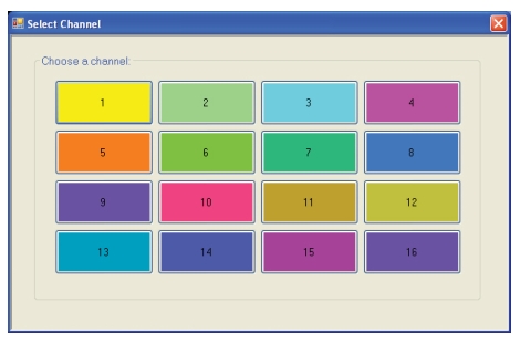
Mixer Setup – Multi-Channel – Frequency Sweep – Channel Assignments
Six channels are required to support all measurements. See Table: Available Measurements for Frequency-Based Sweep above for the default channel assignments. Skipped measurements do not change the channel assignment. For example, if Input Match and Output Match are required in Configuration 1, the default channel assignment will be Channel 1 and Channel 3. The starting channel can be changed to any of the 16 channels. If Channel 16 is assigned, and another channel is required, the Channel assignment rolls over to Channel 1.
Mixer Setup – Multi-Channel – Frequency Sweep – Procedure
1. Navigate to the APPLICATION menu and select the Mixer Setup (Multi-Channel) button.
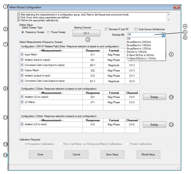
MIXER SETUP CONFIGURATION (FREQUENCY SWEEP) Dialog Box – Control Areas (1 of 2)
1. Dialog Box
2. Select Sweep Type (Frequency or Power Sweep).
3. Channel Start Selection
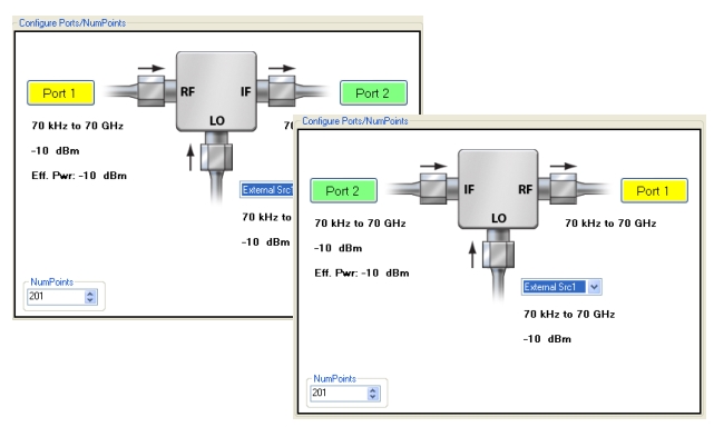
4. Reverse IF and RF – Default is RF as input and IF as output. Toggles to RF as output and IF as input.
5. Modular BB Selections – Only for MS4647B VNAs with Option 8x and ME7838 Series peripheral equipment. Note: All selections are dependent on installed options and model number.
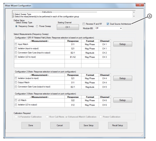
6. Dual Source Architecture (Only for MS464xB VNAs with Option 31) Note that when this feature is selected, the measurement selections change as shown in the figure below.
7. Configuration 1 – Conversion Gain/Loss Swept LO – RF/IF Related Path – Select any combination of measurements. Channels are automatically assigned based on Starting Channel.
8. Setup Button – Links to Configuration 1 Dialogs to configure mixer and VNA ports, external sources, frequency, and power levels.
9. Configuration 2 – Compression Pout versus Pin Swept RF – Select any combination of measurements. Channels are automatically assigned.
10. Setup Button – Links to Configuration 2 Dialogs to configure mixer and VNA ports, external sources, frequency, and power levels.
11. Configuration 3 – Isolation – LO to Input Available Measurement
12. Setup Button – Links to Configuration 3 Dialogs to configure mixer and VNA ports, frequency, and power.
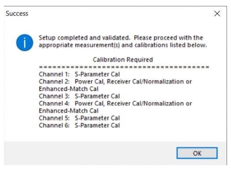
13. Calibration Required Area
14. Dialog Controls Save Setup stores the mixer wizard configuration as a .mwzd file so that it can be recalled at a later time using Recall Setup.
6. Mixer Wizard above shown with Dual Source Architecture feature selected. Note that when this is selected, the measurement selections change.
Mixer Setup – Multi-Channel – Frequency Sweep – Define the Mixer Setup
3. Use the steps below to set the sweep type, the starting channel, reverse ports, and enable modular broadband.
4. In the Define Setup Select Sweep Type area at the top of the dialog, set the Sweep Type as Frequency Sweep.
• If Power Sweep is selected, the dialog box appearance changes.
At top, the standard port assignments of RF on Port 1 as input and IF on Port 2 as output.
At bottom, reversed port assignments of IF on Port 2 and input and RF on Port 1 as output.
Mixer Setup – Multi-Channel – Frequency Sweep – Make Modular BB Selection
8. At the top right of the dialog, make a selection from the Modular BB drop down list.
• Modular BB: Select opens drop down list for selecting various broadband types. This requires using the VectorStar ME7838 Series Broadband/mmWave system with the 3739x BB/mmWave Test Set and two 3743x or MA25x00A mmWave Modules. This is only used on MS4647B VNAs equipped with Option 8x.
The mixer schematic drawing shows the current settings for the RF, IF, and LO ports.
Multi-Channel – SET FREQUENCY (FREQUENCY SWEEP) Setup Dialog Box (1 of 2)
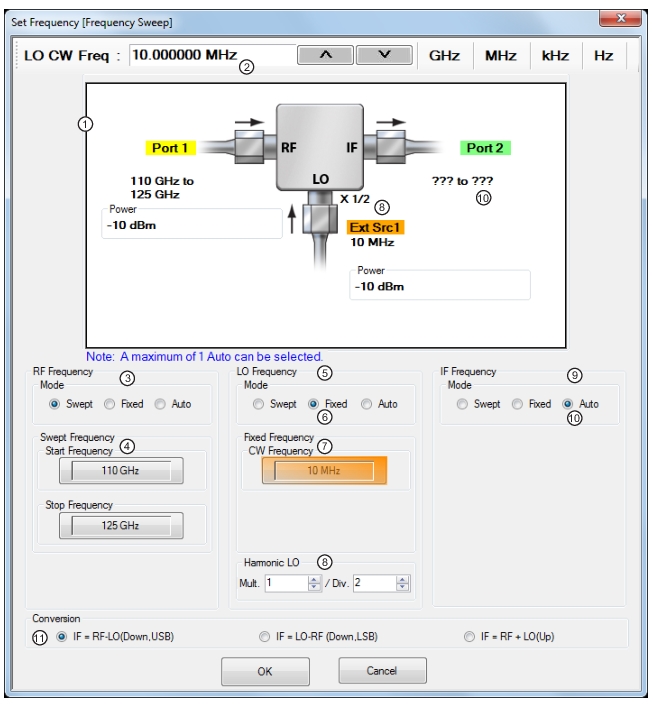
1. Mixer schematic showing mixer and VNA port assignments, frequency values, and power values.
2. Frequency input field toolbar. The label changes depending whether RF, IF, or LO are selected.
3. RF Frequency Mode and Value Settings
4. RF Mode set as Swept with Swept Frequency Start and Stop input field. For all ports, mode can be any combination of Swept and Fixed. Only one port can be set as Auto.
5. LO Frequency Mode and Value Setting
6. LO Mode set as Fixed with CW Frequency input field.
7. LO CW Frequency field tool bar with value and units. Appears for RF, IF, and LO input as required.
8. Harmonic LO: The harmonic LO entry allows one to describe any frequency multiplication and/or division that may be present between the synthesizer providing the LO signal and the DUT's fundamental frequency converter. This entry can also be used when the DUT is a harmonic mixer or sampler that has implicit frequency multiplication in the LO path.
Note: A label showing the Harmonic LO ratio is displayed at the mixer schematic LO port when multiplier/divisor (M/N) ratio is not equal to 1.
9. IF Frequency Mode and Value Settings
10. IF Frequency Mode set as Auto. Only one of the three ports can be set as Auto. If selected, the instrument determines the frequency settings based on the other two values and the Conversion type setting and is displayed in the mixer schematic absent of a frequency label (as shown in the illustration above).
11. Conversion setting radio buttons.
Mixer Setup – Multi-Channel – Frequency Sweep – Configuration 1 – Set Frequency – Set RF, LO, and IF Mode and Values
16. In the middle of the dialog box are separate control areas for RF Frequency, LO Frequency, and IF Frequency.
17. For each control area, set the frequency mode.
• The frequency options are Swept, Fixed, or Auto.
• Any combination of Swept or Fixed can be assigned to the RF, IF, and LO ports.
• Only one port can be configured as Auto. In this configuration, the instrument calculates the required frequency based on the conversion setting selected (described below) in the Conversion area at the bottom of the dialog box and the settings on the other two ports.
• Each Frequency Mode selection provides different control immediately below in the next area.
• In the figure above, RF Frequency is set as Swept, LO Frequency is set as Swept, and IF Frequency is set as Fixed.
18. If the RF, IF, and/or LO Frequency Mode is set as Swept:
• The Swept Frequency area appears with controls for Start Frequency and Stop Frequency.
• Select the Start Frequency field, and at the top of the dialog in the field toolbar, enter the required starting frequency and required units from GHz, MHz, kHz, or Hz.
• Note that the field toolbar name changes depending on whether RF, IF, or LO is selected.
19. If the RF, IF, and/or LO Frequency Mode is set as Fixed:
• The Fixed Frequency area appears with a single control for CW Frequency.
• Select the CW field and enter the required CW frequency and required units.
20. If the RF, IF, or LO Frequency Mode is set as Auto:
• No frequency assignment fields are available.
• The frequency is calculated based on the settings for the other two mixer ports and the settings in the Conversion area described below.
Mixer Setup – Multi-Channel – Frequency Sweep – Configuration 1 – Set Frequency – Harmonic LO
The harmonic LO entry allows one to describe any frequency multiplication and/or division that may be present between the synthesizer providing the LO signal and the DUT's fundamental frequency converter. This entry can also be used when the DUT is a harmonic mixer or sampler that has implicit frequency multiplication in the LO path.
21. Set the Harmonic LO multiplier/divisor ratio. A label showing the Harmonic LO ratio is displayed at the mixer schematic LO port when multiplier/divisor (M/N) ratio is not equal to 1.
Mixer Setup – Multi-Channel – Frequency Sweep – Configuration 1 – Set Frequency – Set the Conversion Required
22. Near the bottom of the dialog is the Conversion area.
23. Select button for the conversion type required from options of:
• IF = RF - LO which is down conversion with Upper SideBand (USB).
• IF = LO - RF which is down conversion with Lower Side Band (LSB).
• IF = RF + LO which is up conversion.
24. When all settings are complete, select the OK button to return to the setup central control dialog.
• The CONFIGURATION 1 SETUP [FREQUENCY SWEEP] setup dialog reappears.
• If any setting is out of range, a warning dialog appears with an error message such as Invalid Frequency Range or Equation Out of Range. Correct the problem as required.
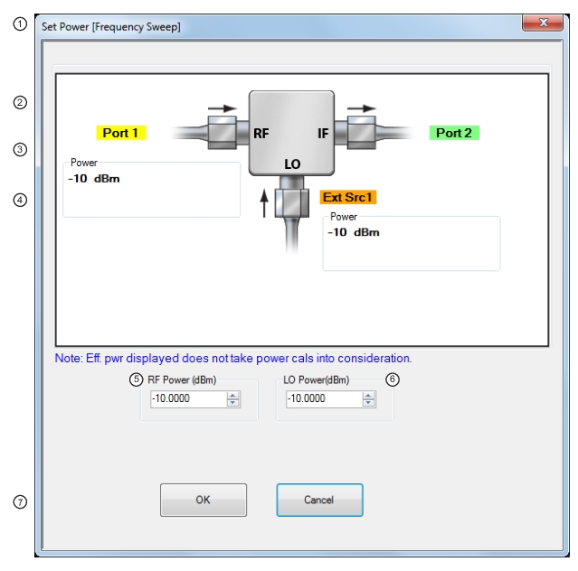
Mixer Setup – Multi-Channel – Frequency Sweep – Configuration 1 – Set Power Levels
25. On the CONFIGURATION 1 SETUP [FREQUENCY SWEEP] setup dialog box, select the Set Power Levels button.