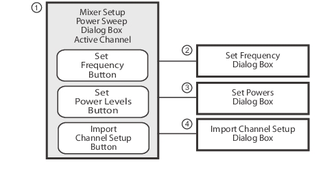
Mixer Setup – Active Channel – Power Sweep – Initial Configuration
4. At the top right of the dialog, make a selection from the Modular BB drop down list.
• Modular BB: Select opens drop down list for selecting various broadband types. This requires using the VectorStar ME7838 Series Broadband/mmWave system with the 3739x BB/mmWave Test Set and two 3743x or MA25x00A mmWave Modules. This is only used on MS4647B VNAs equipped with Option 8x.
5. At the top right of the dialog, select Reverse IF and RF check boxes (if required). The Reverse IF and RF check box changes the input/output assignments for the RF and IF mixer ports.
• The default non-selected check box is RF as input on Port 1 and IF as output on Port 2.
• If selected, the RF is set as output on Port 1 and IF as input on Port 2.
Mixer Setup – Active Channel – Power Sweep – Configure Ports
6. In the Configure Ports area, set the port assignments for the RF, IF, and LO.
• The default assignments are Port 1 = RF, Port 2 = IF, and External Source 1 = LO.
• The port and external source assignments must be unique.
• The assignment options for RF, IF, and LO are:
• Port 1
• Port 2
• Port 3 (4-port VNA)
• Port 4 (4-port VNA)
• External Source (Src) 1
• External Src 2
• External Src 3
• External Src 4
• None
• The changes above are shown in the mixer schematic in the center of the dialog.
MIXER SETUP Dialog Box – 2-port Power Sweep – Control Locations (1 of 2)
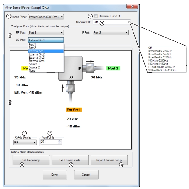
1. Sweep Type Setting – Power Sweep (CW Freq) is set. Options are Freq Sweep (Linear) or Freq (Log).
2. Reverse IF and RF – Default is RF as input, and IF as output. Reverse sets IF as input and RF as output.
3. Modular BB Selections – Only for MS4647B VNAs with Option 8x and ME7838 Series peripheral equipment. Note: All selections are dependent on installed options and model number.
4. Configure Port Assignments – Each must be unique selecting from None, Port 1, Port 2, (and Port 3 or Port 4 for 4-port VNA) or External Sources 1 through 4 (LO Port also has Source 1 or Source 2 available when Option 31 Dual Source Architecture is present).
5. Mixer Schematic – Updates automatically with port assignments, frequency settings, and power levels.
6. X-Axis Display Options – Select from RF, IF, or LO.
7. Num Points (Number of Sweep Points) – Sets the number of sweep points. Shows this setting on the FREQUENCY menu.
8. Set Frequency Button – Select displays the SET FREQUENCY (POWER SWEEP) dialog.
9. Set Power Levels Button – Select displays the SET POWERS (POWER SWEEP) dialog.
10. Import Channel Setup Button – Select imports the active channel settings into the dialogs.
Mixer Setup – Active Channel – Power Sweep – Configure X-Axis Display and Number of Points
7. Set the X-Axis display to the required parameter. The default is RF. Options are RF, IF, or LO.
8. Set the Number of Points (Num Points) for the X-Axis display.
• The initial value is taken from the setting on the FREQUENCY menu and the # of Points button.
• A change on the FREQUENCY menu also changes the setting on the MIXER dialog and a MIXER change changes the FREQUNECY menu setting.
Mixer Setup – Active Channel – Power Sweep – Set RF, LO, and IF Frequency Mode and Value
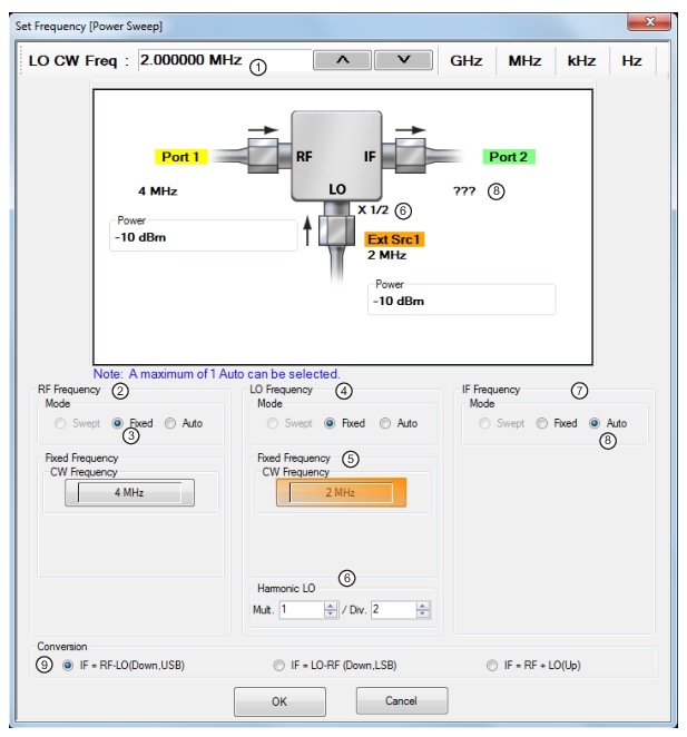
The mixer schematic drawing shows the current settings for the RF, IF, and LO ports.
SET FREQUENCY (POWER SWEEP) Dialog Box – Control Areas
1. Frequency input field toolbar. The label changes depending whether RF, IF, or LO are selected.
2. RF Frequency mode and value area.
3. Mode set as Fixed. Any combination of the RF, IF, and LO ports can be set as Fixed. When selected, a CW Frequency field appears.
4. LO Frequency mode and value area.
5. Mode set as Fixed. Any combination of the RF, IF, and LO ports can be set as Fixed. When selected, a CW Frequency field appears.
6. Harmonic LO: The harmonic LO entry allows one to describe any frequency multiplication and/or division that may be present between the synthesizer providing the LO signal and the DUT's fundamental frequency converter. This entry can also be used when the DUT is a harmonic mixer or sampler that has implicit frequency multiplication in the LO path.
Note: A label showing the Harmonic LO ratio is displayed at the mixer schematic LO port when multiplier/divisor (M/N) ratio is not equal to 1.
7. IF Frequency mode and value area.
8. Mode set as Auto. Only one of the three ports can be set as Auto. If selected, the instrument determines the frequency settings based on the other two values and the Conversion type setting and is displayed in the mixer schematic absent of a frequency label (as shown in the illustration above).
9. Conversion setting. Changes based on whether RF is input or output. If RF is input, equations show conversion calculations for IF. If IF is input, equations show conversion calculations for RF.
Mixer Setup – Active Channel – Power Sweep – RF, LO, and IF Frequency Mode and Value Area
10. In the middle of the dialog box are separate control areas for RF Frequency, LO Frequency, and IF Frequency. Depending on the settings, there is a Mode area and a Frequency area for each port.
11. For each control area, set the frequency mode.
• The frequency options are Fixed or Auto. Swept is not available for Power Sweeps.
• Only one port can be configured as Auto. In this configuration, the instrument calculates the required frequency based on the conversion setting selected in the Conversion area at the bottom of the dialog box and the settings on the other two ports.
• Each Frequency Mode selection provides different input field control immediately below in the next area.
• In the figure above, RF Frequency is set as Swept, LO Frequency is set as Fixed, and IF Frequency is set as Auto.
12. If the RF, IF, and/or LO Frequency Mode is set as Fixed:
• The Fixed Frequency area appears with a single control for CW Frequency.
• Select the CW field and enter the required CW frequency and required units in the field toolbar at the top of the dialog box.
13. If the RF, IF, or LO Frequency Mode is set as Auto:
• No frequency assignment fields are available.
• The frequency is calculated based on the settings for the other two mixer ports and the settings in the Conversion area described below.
Mixer Setup – Active Channel – Power Sweep – Set Frequency – Harmonic LO
The harmonic LO entry allows one to describe any frequency multiplication and/or division that may be present between the synthesizer providing the LO signal and the DUT's fundamental frequency converter. This entry can also be used when the DUT is a harmonic mixer or sampler that has implicit frequency multiplication in the LO path.
14. Set the Harmonic LO multiplier/divisor ratio. A label showing the Harmonic LO ratio is displayed at the mixer schematic LO port when multiplier/divisor (M/N) ratio is not equal to 1.
Mixer Setup – Active Channel – Power Sweep – Set the Conversion Required
15. Near the bottom of the dialog is the Conversion area.
16. Select the button for the conversion type required from options of:
• If RF is input and IF is output (the default):
• IF = RF - LO which is down conversion with Upper Side Band (USB).
• IF = LO - RF which is down conversion with Lower Side Band (LSB).
• IF = RF + LO which is up conversion.
• If RF is output and IF is input (optional):
• RF = IF + LO which is up conversion.
• RF = LO - IF which is down conversion with Lower Side Band (LSB).
• RF = IF - LO which is down conversion with Upper Side Band (USB).
17. When all settings are complete, select the OK button to return to the central control dialog.
• If any setting is out of range, a warning dialog appears with an error message such as Invalid Frequency Range or Equation Out of Range. Correct the problem as required.
Mixer Setup – Active Channel – Power Sweep – Set the Power Levels
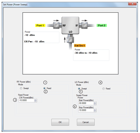
18. Select the Set Power Levels button in the bottom center of the dialog box.
SET POWERS (POWER SWEEP) Dialog Box – Control Areas
1. RF Power (dBm) controls.
2. RF Power Mode set as Fixed with option of Swept.
3. RF Power CW Power input field
4. LO Power controls
5. Mode set as Swept with option of Fixed.
6. Swept Start and Stop power input fields.
Mixer Setup – Active Channel – Power Sweep – Configuring the RF, IF, and LO Power Settings
19. Separate control areas for Mode and Power are provided for RF Power, IF Power, and LO Power.
• If RF is input and IF is output (the default), power level controls are available for RF and LO Power:
• RF Power can be Swept or Fixed. If Swept is set, the Swept Power Start Power and Stop Power input fields are present.If Fixed is set, the Fixed Power input field is present.
• LO Power can be Swept or Fixed. If Swept is set, the Swept Power Start Power and Stop Power input fields are present.If Fixed is set, the Fixed Power input field is present.
• If RF is output and IF is input (optional by selecting the Reverse IF and RF check box):
• IF Power can be Swept or Fixed. If Swept is set, the Swept Power Start Power and Stop Power input fields are present.If Fixed is set, the Fixed Power input field is present.
• LO Power can be Swept or Fixed. If Swept is set, the Swept Power Start Power and Stop Power input fields are present.If Fixed is set, the Fixed Power input field is present.
20. For each displayed mixer port, select the mode as Swept or Fixed.
21. If Swept is set, enter the Start and Stop Power levels.
22. If Fixed is set, enter the CW Power level.
23. Repeat the two steps above for the remaining mixer port.
24. When all settings are complete, select the OK button to return to the main control dialog box.
• The MIXER SETUP (POWER SWEEP) setup dialog reappears.
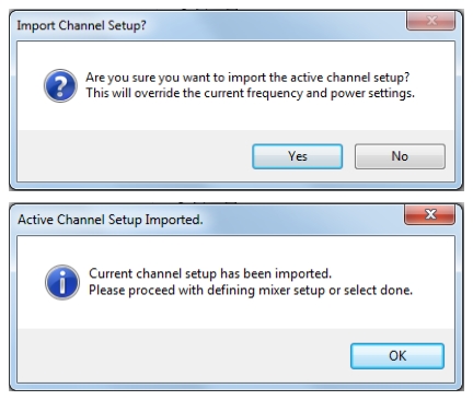
27. Upon completion, the ACTIVE CHANNEL SETUP IMPORTED dialog appears and confirms in configuration import.
ACTIVE CHANNEL SETUP IMPORTED Dialog Box
28. With all settings correct and as required, select the Done button on the MIXER SETUP dialog.
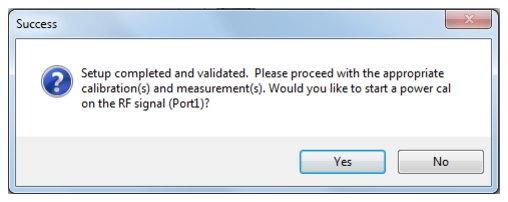
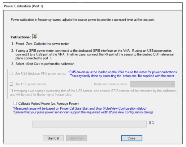
29. A completion message appears as shown below. If a power cal is started, the Power Calibration window shown in Figure: POWER CALIBRATION (PORT 1) Dialog appears.
SUCCESS Dialog with Required Calibrations
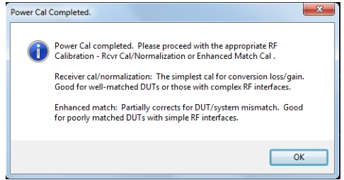
30. Follow the instructions provided in the dialog to complete the Power Calibration. On completion of this cal, the message shown in Figure: POWER CAL Completed Message appears.
POWER CALIBRATION (PORT 1) Dialog
31. Clicking OK on the Power Cal Completed message takes the user to the Manual Cal menu (see MANUAL CAL Menu – 2-Port VNAs), where Receiver Cal Normalization and Enhanced Match selections are made available.
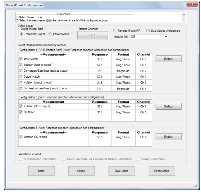
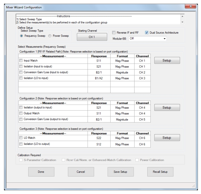
MULTI-CHANNEL MIXER SETUP Dialog Box – Frequency Based Sweep (1 of 2)
This figure shows the Mixer Wizard Configuration dialog when Option 31, Dual Source Architecture is present and the check box shown is selected. Save Setup stores the mixer wizard configuration as a .mwzd file so that it can be recalled at a later time using Recall Setup.
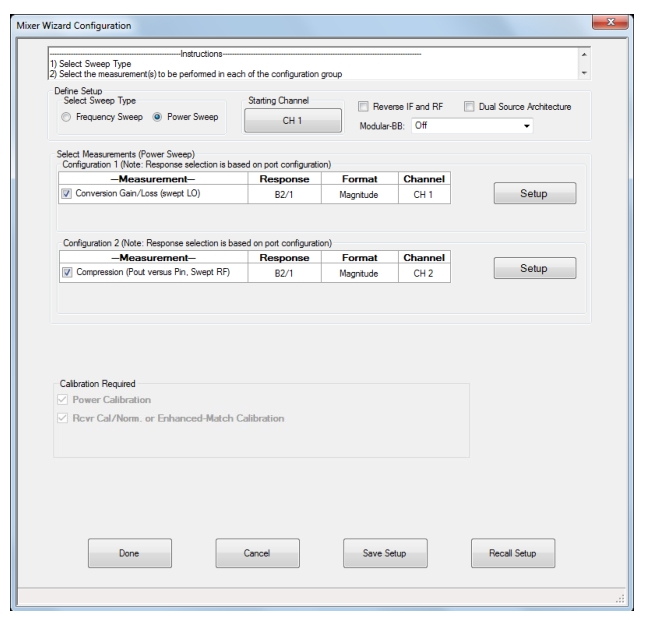
MULTI-CHANNEL MIXER SETUP Dialog Box – Power Sweep
The Mixer Wizard Configuration dialog with Power Sweep selected is the same when Dual Source Architecture is either selected or not selected. Save Setup stores the mixer wizard configuration as a .mwzd file so that it can be recalled at a later time using Recall Setup.