The contents and controls in the dialog box change depending how the user-defined balanced port is selected as:
• Two differential pairs
• One differential pair and one singleton
• One differential pair and two singletons
Each balanced port selection is described in the sections below.
Alternate Mixed Mode Configuration Control
There is a separate mixed-mode response control located on the RESPONSES SETUP menu located within the DISPLAY menus that provides a rapid assignment of one of the three options above. The response type assignment is limited to all traces on the active channel. The menu is described in:
Selecting any option other than Single Ended will place the VNA in DifferentialView mode. Refer to DifferentialView™ (True Mode Stimulus) for more information on configuring DifferentialView.
Define Balanced Port Pair(s)
Select the option required:
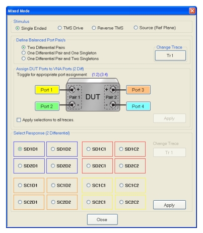
• Two Differential Pairs
The DUT Ports diagram appears with a four-port DUT and is ready for port assignment.
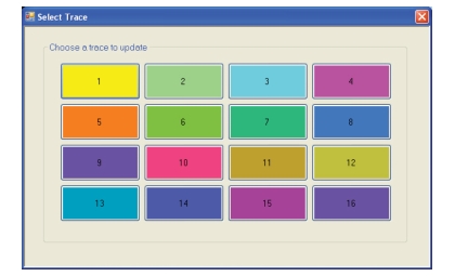
Change Trace
The Change Trace button displays the currently active trace number. Select displays the SELECT TRACE dialog box where another trace can be selected.
For each DUT connection, toggle the Port button to select the appropriate VNA Port Number.
• DUT Port Pair 1
• Pair 1 +: Select from VNA Port 1, Port 2, Port 3, or Port 4. This port has positive polarity.
• Pair 1 –: Select from VNA Port 1, Port 2, Port 3, or Port 4. This port has negative polarity.
• DUT Port Pair 2:
• Pair +: Select from VNA Port 1, Port 2, Port 3, or Port 4
• Pair –: Select from VNA Port 1, Port 2, Port 3, or Port 4
Note that all port assignments must be unique and have different color coding. When all port assignments are completed, select the Apply button. If the assignment is invalid, a warning dialog appears. If the port assignments are valid, the title of the DUT Ports diagram is annotated with the port assignment in the format (A:B):(C:D). For example:
• (1:2):(3:4) = The first port pair is measured from 1 to 2 and the second port pair is measured from 3 to 4.
• (4:1):(2:3) = The first port pair is measured from 4 to 1 and the second port pair is measured from 2 to 3.
Assign Port Assignments to All Traces
The actions above only apply to the active trace on the active channel. If required, select the Apply Selections check box to apply the port pair selections to all traces on the active channel.
Select Responses (2 Differential)
Select the required 2-differential response characteristic from the available 16 combinations of pure differential (D) and common-mode (C) parameters. Only one response may be selected:
• Differential Reception with Differential Drive S-Parameters
• SD1D1 – S-parameter for differential reception at Pair 1 and differential drive at Pair 1.
• SD1D2 – S-parameter for differential reception at Pair 1 and differential drive at Pair 2.
• SD2D1 – S-parameter for differential reception at Pair 2 and differential drive at Pair 1.
• SD2D2 – S-parameter for differential reception at Pair 2 and differential drive at Pair 2.
• Common-Mode Reception with Differential Drive S-Parameters
• SC1D1 – S-parameter for common-mode reception at Pair 1 and differential drive at Pair 1.
• SC1D2 – S-parameter for common-mode reception at Pair 1 and differential drive at Pair 2.
• SC2D1 – S-parameter for common-mode reception at Pair 2 and differential drive at Pair 1.
• SC2D2 – S-parameter for common-mode reception at Pair 2 and differential drive at Pair 2.
• Differential Reception with Common-Mode Drive S-Parameters
• SD1C1 – S-parameter for differential reception at Pair 1 and common-mode drive at Pair 1.
• SD1C2 – S-parameter for differential reception at Pair 1 and common-mode drive at Pair 2.
• SD2C1 – S-parameter for differential reception at Pair 2 and common-mode drive at Pair 1.
• SD2C2 – S-parameter for differential reception at Pair 2 and common-mode drive at Pair 2.
• Common-Mode Reception with Common-Mode Drive S-Parameters
• SC1C1 – S-parameter for common-mode reception at Pair 1 and common-mode drive at Pair 1.
• SC1C2 – S-parameter for common-mode reception at Pair 1 and common-mode drive at Pair 2.
• SC2C1 – S-parameter for common-mode reception at Pair 2 and common-mode drive at Pair 1.
• SC2C2 – S-parameter for common-mode reception at Pair 2 and common-mode drive at Pair 2.
Apply
When the selection is complete, select the Apply button to apply the setting to the active trace.
MIXED MODE Setup Dialog Box – One Diff. Pair – One Singleton – 4-Port VNAs
• Balanced Port Pair Setting = One Differential Pair and One Singleton
Navigation
• MAIN | Response | RESPONSE | Mixed Mode | MIXED MODE Dialog Box | One Differential Pair and One Singleton
MIXED MODE Dialog Box – One Differential Pair and One Singleton – 4-Port VNAs
Stimulus
Select the option required:
• Single Ended
• TMS Drive
• Reverse TMS
• Source (Ref Plane)
Note
Selecting any option other than Single Ended will place the VNA in DifferentialView mode. Refer to DifferentialView™ (True Mode Stimulus) for more information on configuring DifferentialView.
Define Balanced Port Pair(s)
Select the option required:
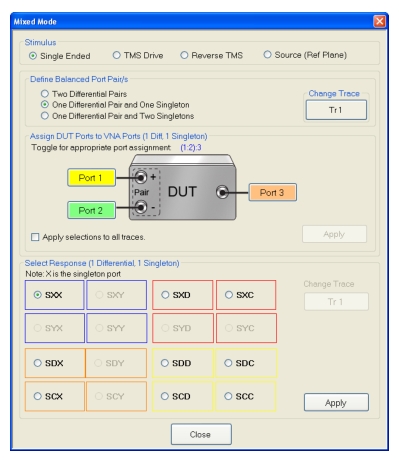
• One Differential Pair and One Singleton
The DUT Ports diagram appears with a DUT having one port pair and one singleton connection.
Change Trace
Displays the currently active trace number. Select displays the SELECT TRACE dialog box where another trace can be selected.
Assign DUT Ports to VNA Ports (1 Diff, 1 Singleton)
For each DUT connection, toggle the Port button to select the appropriate VNA Port Number.
• DUT Port Pair 1
• Pair 1 +: Select from VNA Port 1, Port 2, Port 3, or Port 4. This port has positive polarity.
• Pair 1 –: Select from VNA Port 1, Port 2, Port 3, or Port 4. This port has negative polarity.
• DUT S1 Singleton:
• S1: Select from VNA Port 1, Port 2, Port 3, or Port 4
Note that all port assignments must be unique and have different color coding. When all port assignments are completed, select the Apply button. If the assignment is invalid, a warning dialog appears. If the port assignments are valid, the title of the DUT Ports diagram is annotated with the port assignment in the format (A:B):C). For example:
• (1:2):3 = The DUT port differential is measured from 1 to 2 and 3 is the singleton.
• (4:2):1 = The DUT port differential is measured from 4 to 2 and 1 is the singleton.
Assign Port Assignments to All Traces
The actions above only apply to the active trace on the active channel. If required, select the Apply Selections check box to apply the port pair selections to all traces on the active channel.
Select Response
Select the required differential or common-mode response characteristic from the available 9 combinations of pure differential (D), common-mode (C), or singleton (X) parameters. Only one response may be selected:
• Reception at Singleton and Drive at Singleton
• SXX – S-Parameter for singleton reception and singleton drive.
• Reception at Singleton and Drive at Pair 1
• SXD – S-Parameter for singleton reception and differential drive at Pair 1
• SXC – S-Parameter for singleton reception and common-mode drive at Pair 1
• Reception at Pair 1 and Drive at Singleton
• SDX – S-Parameter for differential reception at Pair 1 and singleton drive
• SCX – S-Parameter for common-mode reception at Pair 1 and singleton drive
• Reception at Pair 1 and Drive at Pair 1
• SDD – S-Parameter for differential reception at the Pair 1 and differential drive at the port pair.
• SDC – S-Parameter for differential reception at Pair 1 and common-mode drive at the port pair
• SCD – S-Parameter for common-mode reception at Pair 1 and differential drive at the port pair.
• SCC – S-Parameter for common-mode reception at Pair 1 and common-mode drive at the port pair.
Apply
When the selection is complete, select the Apply button to apply the setting to the active trace.
MIXED MODE Setup Dialog Box – One Diff. Pair – Two Singletons – 4-Port VNAs
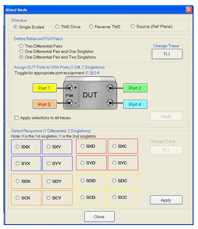
Assign DUT Ports to VNA Ports (1 Diff, 1 Singleton)
For each DUT connection, toggle the Port button to select the appropriate VNA Port Number:
• DUT Port Pair 1
• Pair 1 +: Select from VNA Port 1, Port 2, Port 3, or Port 4. This port has positive polarity.
• Pair 1 –: Select from VNA Port 1, Port 2, Port 3, or Port 4. This port has negative polarity.
• DUT S1 Singleton:
• S1: Select from VNA Port 1, Port 2, Port 3, or Port 4
• DUT S2 Singleton:
• S2: Select from VNA Port 1, Port 2, Port 3, or Port 4
Note that all port assignments must be unique and have different color coding. When all port assignments are completed, select the Apply button. If the assignment is invalid, a warning dialog appears. If the port assignments are valid, the title of the DUT Ports diagram is annotated with the port assignment in the format (A:B):C). For example:
• (1:2):3:4 = The DUT port differential is measured from 1 to 2 while 3 and 4 are the singletons.
• (4:2):1:3 = The DUT port differential is measured from 4 to 2 while 1 and 3 are the singletons.
Assign Port Assignments to All Traces
The actions above only apply to the active trace on the active channel. If required, select the Apply Selections check box to apply the port pair selections to all traces on the active channel.
Select Response
Select the required differential or common-mode response characteristic from the available 16 combinations of pure differential (D), common-mode (C), first singleton (X), or second singleton (Y) parameters. Only one response may be selected:
• Reception at Singleton and Drive at Singleton
• SXX – S-Parameter for first singleton reception and first singleton drive
• SXY – S-Parameter for first singleton reception and second singleton drive
• SYX – S-Parameter for second singleton reception and first singleton drive
• SYY – S-Parameter for second singleton reception and second singleton drive
• Reception at Singleton and Drive at Pair 1
• SXD – S-Parameter for first singleton reception and differential drive at Pair 1
• SXC – S-Parameter for first singleton reception and common-mode drive at Pair 1
• SYD – S-Parameter for second singleton reception and differential drive at Pair 1
• SYC – S-Parameter for second singleton reception and common-mode drive at Pair 1
• Reception at Pair 1 and Drive at Singleton
• SDX – S-Parameter for differential reception at Pair 1 and first singleton drive
• SDY – S-Parameter for differential reception at Pair 1 and second singleton drive
• SCX – S-Parameter for common-mode reception at Pair 1 and first singleton drive
• SCY – S-Parameter for common-mode reception at Pair 1 and second singleton drive
• Reception at Pair 1 and Drive at Pair 1
• SDD – S-Parameter for differential reception at Pair 1 and differential drive at the port pair.
• SDC – S-Parameter for differential reception at Pair 1 and common-mode drive at the port pair.
• SCD – S-Parameter for common-mode reception at Pair 1 and differential drive at the port pair.
• SCC – S-Parameter for common-mode reception at Pair 1 and common-mode drive at the port pair.
Apply
When the selection is complete, select the Apply button to apply the setting to the active trace.
Select the trace number button to apply the current mixed-mode settings. After a Trace Number button is selected, the focus auto returns to the MIXED MODE dialog box.