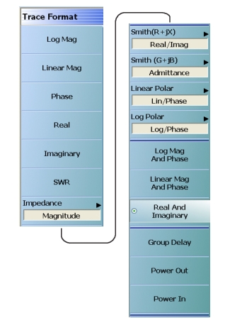
Select sets a dual rectilinear display with Log Magnitude data in the upper graph and Phase data in the lower graph.
Linear Mag and Phase (Trace Format)
Select sets a dual rectilinear display with Linear Magnitude data in the upper graph and Phase data in the lower graph.
Real and Imaginary (Trace Format)
Select sets a dual rectilinear display with Real data in the upper graph and Imaginary data in the lower graph.
Group Delay (Trace Format)
Group delay graphs display phase-related distortion as a function of frequency such as for the flatness of the group delay of a filter over its passband. Select sets a single rectilinear display.
Power Out (Trace Format)
Select sets a single rectilinear display measuring power output of the DUT.
Power In (Trace Format)
Select sets a single rectilinear display measuring power input to the DUT.
IMPEDANCE Menu
With the Impedance menu item selected as the trace format, the selected trace display is redrawn according to the selected impedance type. The trace annotation and scaling changes accordingly.
• MAIN | Display | DISPLAY | Trace Format | TRACE FORMAT | Impedance | IMPEDANCE
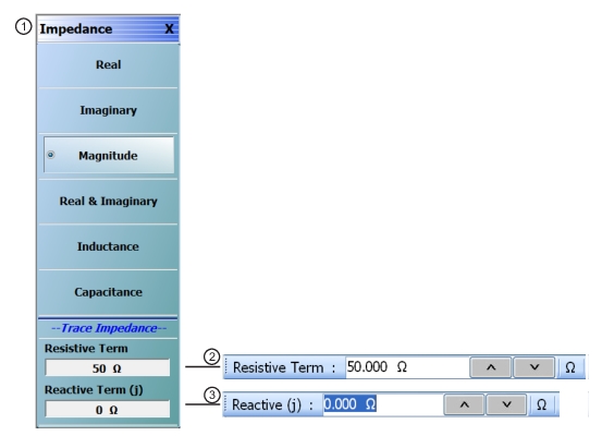
IMPEDANCE Menu
1. IMPEDANCE Menu
2. Resistive Term Field Toolbar in Ohms.
3. Reactive (j) Term Field Toolbar in Ohms.
Auto-Return Button Selection Group
• The first six (6) buttons (Real, Imaginary, Magnitude, Real & Imaginary, Inductance, and Capacitance) on the IMPEDANCE menu are configured as a button selection group with an auto-return function, where selection of any one button de-selects the other five (5) buttons, and then auto-returns to the TRACE FORMAT Menu, which then displays the currently selected impedance. The selected impedance is also displayed on the Trace Format button of the DISPLAY Menu.
Real (Impedance)
Select sets a rectilinear display, de-selects the previously selected impedance type, then auto-returns to TRACE FORMAT menu.
Imaginary (Impedance)
Select sets a rectilinear display, de-selects the previously selected impedance type, then auto-returns to TRACE FORMAT menu.
Magnitude (Impedance)
Select sets a rectilinear display, de-selects the previously selected impedance type, then auto-returns to TRACE FORMAT menu.
Real & Imaginary (Impedance)
Select sets a dual rectilinear display with Real data in the upper graph and Imaginary data in the lower graph. Select also de-selects the previously selected impedance type, then auto-returns to TRACE FORMAT menu.
Inductance (Impedance)
Select sets a rectilinear display, de-selects the previously selected impedance type, then auto-returns to TRACE FORMAT menu.
Capacitance (Impedance)
Select sets a rectilinear display, de-selects the previously selected impedance type, then auto-returns to TRACE FORMAT menu.
Resistive Term (Ohms)
Select allows the user to enter the trace impedance in Ohms and displays the Resistive Term toolbar. Use the toolbar to enter the required impedance for the currently active trace. The default value is 50.000 Ohms.
Reactive (j) (Ohms)
Select allows the user to enter trace reactive term in Ohms and displays the Reactive (j) toolbar.
• MAIN | Scale | SCALE | Scale Selection | SMITH SCALING
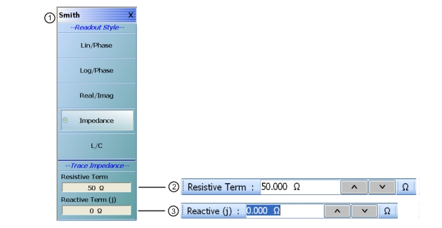
SMITH (IMPEDANCE) Menu
1. SMITH (IMPEDANCE) Menu
2. Resistive Term Field Toolbar in Ohms.
3. Reactive (j) Term Field Toolbar in Ohms.
Auto-Return Button Selection Group
• The Lin/Phase, Log/Phase, Real/Imag, and Impedance buttons form a button selection group with an auto-return function, where the selection of any one button de-selects the other three buttons and auto-returns to the TRACE FORMAT menu.
Lin/Phase (Smith Impedance)
Select creates a Smith Chart (Impedance) that plots with linear values and phase.
Log/Phase (Smith Impedance)
Select creates a Smith Chart (Impedance) that plots with log values and phase.
Real/Imag (Smith Impedance)
Select creates a Smith Chart (Impedance) that plots with real and imaginary values.
Impedance (Smith Impedance)
Select creates a Smith Chart (Impedance) that plots only impedance.
L/C (Smith Impedance)
Select creates a Smith Chart (Impedance) that plots with inductance and capacitance.
Resistive Term (Smith Impedance)
Select displays the Resistive Term (Ohms) toolbar and allows the user to select the impedance for the selected active trace.
Reactive Term (j) (Smith Impedance)
Select displays the Reactive Term (j) Field Toolbar (Smith Impedance). The appearance and operation is the same as the Resistive Term field toolbar above.
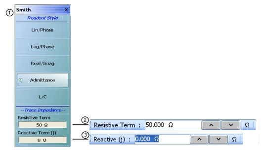
SMITH (ADMITTANCE) Menu
The Lin/Phase, Log/Phase, Real/Imag, and Admittance buttons form an auto-return button selection group where the selection of any one button de-selects the other three buttons and auto-returns to the TRACE FORMAT menu.
• MAIN | Display | DISPLAY | Trace Format | TRACE FORMAT | Smith (G+jB) | SMITH (ADMITTANCE)
SMITH (ADMITTANCE) Menu
‘
1. SMITH (ADMITTANCE) Menu
2. Resistive Term Field Toolbar in Ohms.
3. Reactive (j) Term Field Toolbar in Ohms.
Lin/Phase (Smith Admittance)
Select creates a Smith Chart (Admittance) that plots with linear values and phase.
Log/Phase (Smith Admittance)
Select creates a Smith Chart (Admittance) that plots with log values and phase.
Real/Imag (Smith Admittance)
Select creates a Smith Chart (Admittance) that plots with real and imaginary values.
Admittance (Smith Admittance)
Select creates a Smith Chart (Admittance) that plots only admittance.
L/C (Smith Admittance)
Select creates a Smith Chart (Admittance) that plots with inductance and capacitance values.
Resistive Term (Smith Admittance)
Select displays the Resistive Term (Ohms) toolbar and allows the user to select the impedance for the trace.
Reactive Term (j) (Smith Admittance)
Select displays the Reactive Term (j) Field Toolbar (Smith Impedance). The appearance and operation is the same as the Resistive Term field toolbar above.
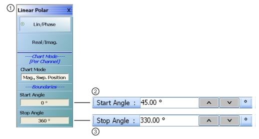
On a per-channel basis, select toggles between values of Mag/Phase and Mag/Swp. Position. If Mag/Phase is selected, the Start Angle and Stop Angle buttons below are unavailable. If Mag/Swp. Position is selected, the Start Angle and Stop Angle buttons are become available.
Start Angle (Linear Polar)
The Chart Mode toggle button must be set to Mag/Phase for this button to be available. Select displays the Start Angle (Degrees) toolbar. Enter a starting angle between 0.00 degrees and 360 degrees.
Stop Angle (Linear Polar)
The Chart Mode toggle button must be set to Mag/Phase for this button to be available. Select displays the Stop Angle (Degrees) toolbar. Enter a stop angle from between 0.00 degrees and 360 degrees.
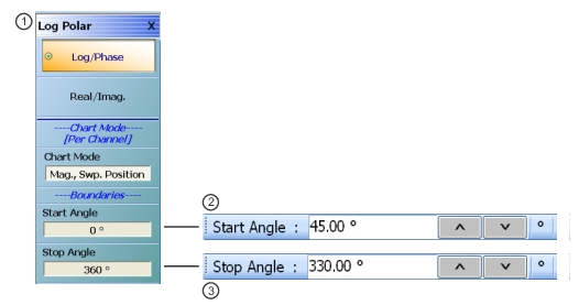
On a per-channel basis, select toggles between values of Mag/Phase and Mag/Swp. Position. If Mag/Phase is selected, the Start Angle and Stop Angle buttons below are unavailable. If Mag/Swp. Position is selected, the Start Angle and Stop Angle buttons are become available.
Start Angle (Deg) (Log Polar)
The Chart Mode toggle button must be set to Mag/Phase for this button to be available. Select displays the Start Angle (Degrees) toolbar. Enter a starting angle between 0.00 degrees and 360 degrees.
Stop Angle (Log Polar)
The Chart Mode toggle button must be set to Mag/Phase for this button to be available. Select displays the Stop Angle (Degrees) toolbar. Enter a stop angle from between 0.00 degrees and 360 degrees.
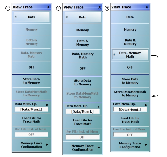
• If trace data has not previously been stored to memory, only the Data, Off, Store Data to Memory, and Data Mem Op buttons (all described below) are available as shown left side of Figure: VIEW TRACE Menu below.
• The Memory, Data & Memory, Data Memory Math, and Store Data Mem Math to Memory buttons are unavailable.
• After one or more sweeps, select the Store Data to Memory button to enable the Memory, Data & Memory, Data Memory Math buttons.
• See the section below for availability of the Store Data Mem Math to Memory button functions.
VIEW TRACE Menu
1. VIEW TRACE menu button availability with no data stored to memory.
2. VIEW TRACE menu after one or more sweeps and Store Data to Memory has been selected.
Button Selection Group
• If trace data has been stored to memory, the Data, Memory, Data and Memory, Data Mem. Math, and OFF buttons become available and form a button selection group where selection of any one button de-selects the other four buttons, as shown in the right side of Figure: VIEW TRACE Menu.
View Trace Button Availability
If trace data has not previously been stored to memory, only the Data, Off, Store Data to Memory, and Data Mem Op buttons are available.
Data
The button is available but has no function until data has been stored as described below.
OFF (View Trace)
If OFF (View Trace) is selected, the active trace on the active channel is removed from the trace graph display.
Store Data to Memory
Select causes data to be stored to memory and the Store Data MemMath to Memory button is (below) becomes available.
After one or more sweeps, select the Store Data to Memory button to enable the Memory, Data & Memory, Data Memory Math buttons described below.
View Trace Menu Button Selection Group
If data has been saved to memory, the Data, Memory, Data and Memory, Data Mem. Math, and OFF buttons become available and form a button selection group where selection of any one button de-selects the other four buttons.
Data
Select records data to memory where it can be stored or further manipulated. The Store Data MemMath to Memory button (below) is unavailable.
Memory
Memory recalls data from memory where it is displayed or further manipulated. The Store Data MemMath to Memory button (below) is unavailable. Saved memory location information will be displayed along with the trace annotation when Memory is selected as the View Trace mode.
Data & Memory
Data & Memory recalls data and uses the active memory for display and/or further manipulation. The Store Data MemMath to Memory button (below) is unavailable.
Data Memory Math
The Data Memory Math button enabled the Store Data MemMath to Memory button (below) is available where the selected math operation is applied to the stored data.
OFF (View Trace)
If OFF (View Trace) is selected, the active trace on the active channel is removed from the trace graph display. The Store Data MemMath to Memory button (below) is unavailable.
Store Data to Memory
Select causes data to be stored to memory and the Store Data MemMath to Memory button is (below) is available.
Store Data MemMath to Memory
The Data Memory Math button (above) must be selected to make this button available. If selected, this stored the active trace data/math information to a file.
• MAIN | Display | DISPLAY | View Trace | VIEW TRACE | Data Mem Op | DATA MEM OP
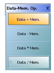
DATA-MEM. OP. (DATA-MEMORY OPERATIONS) Menu
Button Selection Group
• The menu buttons formbutton selection group where the selection of any one button de-select the other three buttons.
Data + Mem. (Plus)
Selecting Data + Mem button de-selects the Data – Mem, Data Mem, and Data / Mem buttons. The data value is added to the memory value. Click Back to return to the View Trace menu.
Data – Mem. (Minus)
Selecting the Data – Mem button de-selects the Data + Mem, Data Mem, and Data / Mem buttons. The memory value is subtracted from the data value. Click Back to return to the View Trace menu.
Data * Mem. (Multiplication)
Selecting Data * Mem button de-selects the Data + Mem, Data – Mem, and Data / Mem buttons. The data value is multiplied times the memory value. Click Back to return to the View Trace menu.
Data / Mem. (Division)
Selecting Data / Mem button de-selects the Data + Mem, Data – Mem, and Data Mem buttons. The data value is divided by the memory value. Click Back to return to the View Trace menu.
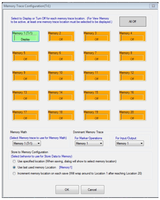
The matrix in the upper portion of the dialog controls which memories are visible in the current trace (current trace denoted in the title of the dialog) when the display selection is either Memory or Data and Memory.
Tr# represents the selected trace number. The memory buttons in the MEMORY TRACE CONFIGURATION dialog are enabled when the user saves data of a particular trace to the corresponding memory location.
All Off
Selecting the All Off button turns off all memory trace locations. For View Memory to be active, at least one memory trace location must be selected to be displayed.
Memory 1 ... Memory 20
Select a Memory # button to enable/disable display of stored trace data from that memory location. Each box is a toggle button to display or not display the memory, and a given button will only be active if something has been stored in that location. The trace where that stored data originally came from will be shown in parentheses.
Memory Math
Selects which memory will be used for a math operation of the form DataMemMath. The various locations will only be available if something has been stored in that location.
Dominant Memory Trace
Select dominant memory trace for marker operations and for input/output.
If only memory is displayed, the markers will traverse on the Memory selected in “For Marker Operations”. The Memory selected in “For Input/Output” will be used for when saving memory data.
• Active Trace Memory 1 [Formatted](*.tdf)
• Active Trace Memory 1 [UnFormatted](*.tdu)
Store to Memory Configuration
Select behavior to use for Store Data to Memory operations:
• Use specified location – Allows user to select a particular memory location to which the data is to be stored. A dialog box will displayed every time “Stored Data to Memory” is selected.
• Use last used memory location (default) – Saves the data to the last saved memory location (the location with the same number as the active trace).
• Increment memory location on each save – Saves the data in the next available memory location in an incremental order, beginning with the last used location for that trace. Note that when the 20 locations have been used, the oldest stored information will be overwritten and the saving will continue cyclically.