• MAIN | Display | DISPLAY | Domain | DOMAIN Frequency with Time Gate | Range Setup | RANGE SETUP Frequency with Time Gate | Window Shape | WINDOW SHAPE
• MAIN | Display | DISPLAY | Domain | DOMAIN Time Band Pass | Range Setup | RANGE SETUP Time Band Pass | Window Shape | WINDOW SHAPE
• MAIN | Display | DISPLAY | Domain | DOMAIN Time Low Pass | Range Setup | RANGE SETUP Time Low Pass
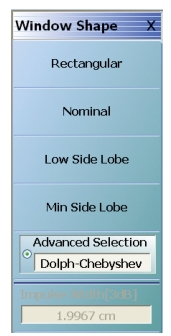
WINDOW SHAPE Menu
WINDOW SHAPE Menu Button Selection Group
The Rectangular, Nominal, Low Side Lobe, Min Side Lobe, and Advanced Selection buttons form a five (5) button selection group where selection of any one button de-selects the other three buttons.
• On the DOMAIN menu, Domain Type is set to one of the following: Frequency, with Time Gate; Time, Band Pass; Time, Low Pass
• Time Low Pass requires on the FREQUENCY menu, a harmonic sweep set such as: Start Frequency = 10 MHz; Stop Frequency = 50 MHz; # of Points = 5 points
• MAIN | Display | DISPLAY | Domain | DOMAIN Frequency with Time Gate | Range Setup | RANGE SETUP Frequency with Time Gate | Window Shape | WINDOW SHAPE | Advanced Selection | ADVANCED WINDOW SHAPE SETUP Dialog Box
• MAIN | Display | DISPLAY | Domain | DOMAIN Time Band Pass | Range Setup | RANGE SETUP Time Band Pass | Window Shape | WINDOW SHAPE | Advanced Selection | ADVANCED WINDOW SHAPE SETUP Dialog Box
• MAIN | Display | DISPLAY | Domain | DOMAIN Time Low Pass | Range Setup | RANGE SETUP Time Low Pass | Window Shape | WINDOW SHAPE | Advanced Selection | ADVANCED WINDOW SHAPE SETUP Dialog Box
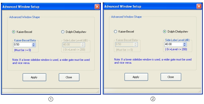
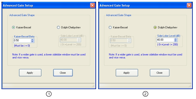
ADVANCED WINDOW SHAPE SETUP Dialog Box
1. ADVANCED WINDOW SETUP – Advanced Window Shape dialog box for Kaiser-Bessel at left.
2. ADVANCED WINDOW SETUP – Advanced Window Shape dialog box for Dolph-Chebyshev at right.
Instructions
The Advanced Window Shape area provides a two-button selection group (Kaiser-Bessel or Dolph-Chebyshev) where the selection of one button de-selects the other button. If selected, each button provides an additional configuration parameter.
Note
If a lower side-lobe window is used, a wider gate must be used. If a higher side-lobe window is used, a narrower gate must be used.
1. Make a selection of one of the two available choices.
• Kaiser-Bessel
• Dolph-Chebyshev
2. If Kaiser-Bessel is selected, the Kaiser-Bessel Beta area below the button becomes available.
• Either use the up/down arrows to select a pre-defined value, or enter a value from the front panel or keyboard.
• Note that the input value must be ≥ 0 (greater than or equal to zero).
3. If Dolph-Chebyshev is selected, the Side-Lobe Level (dB) area button becomes available.
• Either use the up/down arrows to select a pre-defined value, or enter a value from the front panel or keyboard.
• Note that the input value must be 0 ≥ Level ≥ 200 (greater than or equal to zero and less than or equal to 200).
4. Click Apply to set the changes.
• If you click Close without clicking the Apply button, any dialog box changes are discarded and the prior window shape state is retained.
5. Click Close to close the dialog box and return to the ADVANCED WINDOW SHAPE SETUP dialog box.
• On the DOMAIN menu, Domain Type is set to one of the following: Frequency, with Time Gate; Time, Band Pass; Time, Low Pass.
• Time Low Pass requires on the FREQUENCY menu, a harmonic sweep setup such as: Start Frequency = 10 MHz; Stop Frequency = 50 MHz; # of Points = 5 points
• MAIN | Display | DISPLAY | Domain | DOMAIN Frequency with Time Gate | Gate Setup | GATE SETUP
• MAIN | Display | DISPLAY | Domain | DOMAIN Time Band Pass | Gate Setup | GATE SETUP
• MAIN | Display | DISPLAY | Domain | DOMAIN Time Low Pass | Gate Setup | GATE SETUP
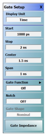
GATE SETUP Menu
GATE SETUP Menu Button Units
The units of the GATE SETUP menu and its Start, Stop, Center, and Span buttons change between Distance or Time, depending on the setting of the Display Unit toggle button. This button is shared by the GATE SETUP and the RANGE SETUP menus. The GATE SETUP (Distance) menu is shown at left.
• See the RANGE SETUP menu above for an example of time setup values in a menu.
The RANGE SETUP and the GATE SETUP menus use the same Display Unit button setting. Changing the Display Unit setting on one menu changes the other menu setting to an identical setting.
Select toggles between distance and time. When toggled to Distance, the Start, Stop, Center, and Span button fields show distance values as described in the buttons below.
Start (Distance/Time) (Gate)
If the Display Unit toggle button is set to distance, select displays the Start (Distance) toolbar.
If the Display Unit toggle button is set to time, select displays the Start (Time) toolbar.
Stop (Distance/Time) (Gate)
As above, select either displays the Stop (Distance) or Stop (Time) toolbar.
Center (Time or Distance) (Gate)
As above, select either displays the Center (Distance) or Center (Time) toolbar.
Span (Time or Distance) (Gate)
As above, select either the Span (Distance) or Span (Time) toolbar.
• MAIN | Display | DISPLAY | Domain | DOMAIN Frequency with Time Gate | Gate Setup | GATE SETUP | Gate Function | GATE FUNCTION
• MAIN | Display | DISPLAY | Domain | DOMAIN Time Band Pass | Gate Setup | GATE SETUP | Gate Function | GATE FUNCTION
• MAIN | Display | DISPLAY | Domain | DOMAIN Time Low Pass | Gate Setup | GATE SETUP | Gate Function | GATE FUNCTION
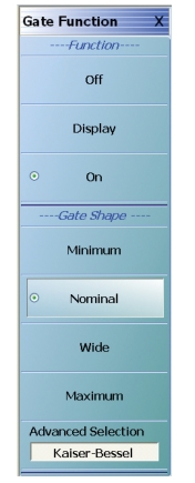
GATE FUNCTION Menu
GATE Function Area Button Selection Group
The three (3) Gate Function Area buttons (Off, Display, and On) form a button selection group where the selection of any one button de-selects the other two buttons.
Off (Gate Function)
Select turns OFF the gate function on the active trace.
Display (Gate Function)
Select displays the gate function on the active trace
On (Gate Function)
Select turns ON the gate function on the active trace.
Gate Shape Area Button Selection Group
The four (4) Gate Shape Area buttons (Minimum, Nominal, Wide, Maximum, and Advanced Selection) form a button selection group where the selection of any one button de-selects the other four buttons.
Minimum (Gate Function)
Select sets the gate function to its minimum setting.
Nominal (Gate Function)
Select sets the gate function to its nominal setting.
Wide (Gate Function)
Select sets the gate function to its widest setting.
Maximum (Gate Function)
Select sets the gate function to its maximum setting.
Advanced Selection (Gate Function)
Select displays the Advanced Gate (Shape) Setup dialog box which allows selection either of a Kaiser-Bessel or Dolph-Chebyshev shaped gate. Each gate option allows selectable parameters.
• MAIN | Display | DISPLAY | Domain | TIME DOMAIN | Gate Setup | GATE SETUP | Gate Function | GATE FUNCTION | Advanced Selection | ADVANCED GATE (SHAPE) SETUP Dialog Box
ADVANCED GATE SHAPE SETUP Dialog Box
1. ADVANCED WINDOW SETUP – Advanced Gate Shape dialog box for Kaiser-Bessel at left.
2. ADVANCED WINDOW SETUP – Advanced Gate Shape dialog box for Dolph-Chebyshev at right.
Button Selection Group
The Advanced Gate Shape area provides a two-button selection group (Kaiser-Bessel or Dolph-Chebyshev) where the selection of one button de-selects the other button. If selected, each button provides an additional configuration parameter.
Note
If a lower side-lobe window is used, a wider gate must be used. If a higher side-lobe window is used, a narrower gate must be used.
1. Make a selection of one of the two available choices.
• For the Calculate Local Impedance button to be active, Modify Gate Start or Modify Gate Stop must be checked and the Domain Mode must be set to Time Low Pass.
• Local and reference impedances must be positive real.
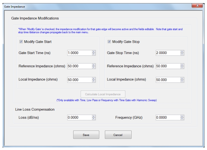
When a gate starts or stops in a region whose impedance is not the reference impedance (usually 50 ohms), there can be some complications in interpreting the Frequency-with-time-gate result.
TheGATE IMPEDANCE Dialog Box provides a means to re-reference the impedance at either end of the gate to something that might be more desirable (often the calibration reference impedance which is usually 50 ohms). This process works by synthetically introducing impedance transitions at gate start and/or gate stop to get the net result back to the desired impedance planes.
Modify Gate Start Area
Note
Depending whether Time or Distance is selected on the Display Unit field of the Gate Setup menu, the Dialog will show either Gate Start/Stop (in time units) or Gate Start/Stop (in distance units).
• Gate Start Time (or Distance)
• Set the gate start time (or distance) to the desired value that will properly re-reference the impedance.
• Reference Impedance
• Set this to the typical impedance of the line (usually 50 ohms).
• Local Impedance
• Set this to the known non-typical value of impedance along the line. If it is unknown, use the Calculate Local Impedance tool.
Modify Gate Stop Area
• Gate Stop Time (or Distance)
• Set the gate stop time (or distance) to the desired value that will properly re-reference the impedance.
• Reference Impedance
• Set this to the typical impedance of the line (usually 50 ohms)
• Local Impedance
• Set this to the known non-typical value of impedance along the line. If it is unknown, use the Calculate Local Impedance tool.
Calculate Local Impedance
• Calculate Local Impedance button is enabled if Modify Gate Start or Modify Gate Stop is checked and the Domain Mode (also accessed via the DISPLAY Menu) is set to Time Low Pass.
When selected, the system will calculate the local impedance at gate start and stop locations. This calculation is based on a step response integration of the current data and can be helpful if the DUT impedance levels are not precisely known. Note that if the gate start or stop are placed very close (within a few impulse widths) to physical impedance transitions, the accuracy of this calculation will be reduced.
Line Loss Compensation
• Set the Loss and Frequency to desired values.
If the DUT is lossy, the synthetic modifications should be based on that loss level as well as the impedances involved and the loss-per-unit length at a specific frequency can be entered here. A square-root-of-frequency dependence will be assumed and the loss will be treated as being equally distributed along the length of the DUT (up until gate stop).