VectorStar™ MS464xB Series Microwave Vector Network Analyzer User Interface Reference : Marker Menus : Primary Marker Menus
 
Primary Marker Menus
MARKERS [1] Menu
Previous
MAIN Menu
SPA SETUP Menu
Navigation
MAIN | Marker | MARKERS [1]
MARKERS [1] Menu (1 of 2)
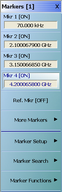
Mkr 1 [Ref] [OFF/ON]
The Marker 1 Button appearance depends on instrument settings:
If the label reads Mkr 1 [OFF], Marker 1 is set to off.
If the label reads Mkr 1 [ON], Marker 1 is set to on.
If the label reads Mkr1-Ref [OFF], the Ref. Mkr button (described below) is set to on, and Marker 1 is set to off.
If the label reads Mkr1-Ref [ON], the Ref. Mkr button is set to on, and Marker 1 is set to on.
If the marker button reads Mkr1-Ref1[ON], the Mkr1-Ref [ON] Toolbar is available. Allows input of frequency value and selection of GHz, MHz, kHz, or Hz units.
Mkr 2 [Ref] [OFF/ON]
Used to control Marker 2. The button is similar in appearance and operation to the Mkr 1 [Ref] [OFF/ON] button above.
Mkr 3 [Ref] [OFF/ON]
Used to control Marker 3. The button is similar in appearance and operation to the Mkr 1 [Ref] [OFF/ON] button above.
Mkr 4 [Ref] [OFF/ON]
Used to control Marker 4. The button is similar in appearance and operation to the Mkr 1 [Ref] [OFF/ON] button above.
Ref. Mkr [OFF/ON]
Select toggles the reference marker off and on.
Ref. Mkr ON
If toggled to ON, a user-defined reference value can be entered and:
The labels for the Mkr 1, Mkr 2, Mkr 3, and Mkr 4 buttons (described above) change to Mkr1-Ref, Mkr2-Ref, Mkr3-Ref, and Mkr4-Ref.
The labels for Mkr 5 through Mkr 12 on the Markers [2] menu (described below) are changed to Mkr5-Ref through Mkr12-Ref.
The Ref. Mkr [ON] toolbar appears below the icon toolbar.
The units in the reference marker toolbar depend on the sweep, domain, and time/distance settings.
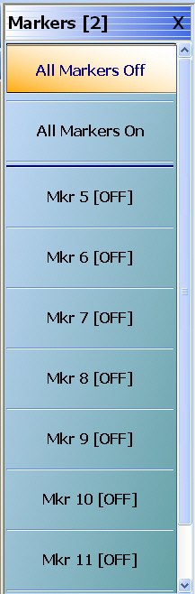
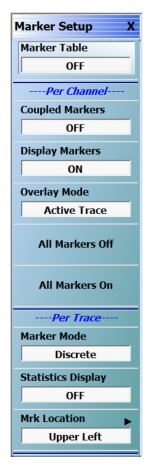
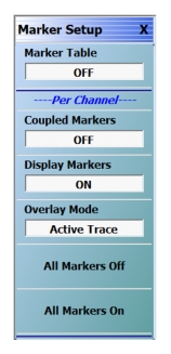
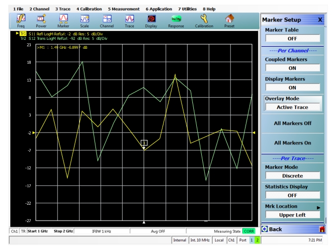
 
Ref. Mkr OFF
If toggled to OFF:
The labels for the Mkr1-Ref, Mkr2-Ref, Mkr3-Ref, and Mkr4-Ref buttons change to Mkr 1, Mkr 2, Mkr 3, and Mkr 4.
The labels for Mkr5-Ref through Mkr12-Ref. on the Markers [2] menu change to Mkr 5 through Mkr 12.
The menu changes automatically from the Markers [1] menu to the Markers [2] menu.
More Markers
Select displays the MARKERS [2] menu and the controls for Marker 5 through Marker 12. The button labels for these markers are the same as Marker 1 through Marker 4.
Markers Setup
Select displays the MARKER SETUP menu.
Markers Search
Select displays the MARKER SEARCH button.
Marker Functions
Select displays the MKR FUNCTIONS menu.
MARKERS [2] Menu
Previous
MARKERS [1] Menu
Navigation
MAIN | Marker | MARKERS [1] | More Markers | MARKERS [2]
MARKERS [2] Menu 
All Markers Off
Select toggles all 12 regular markers off. If on, Reference Marker is turned off.
All Markers On
Select toggles all 12 regular markers on. If OFF, the Reference Marker is not turned on. If ON, the Reference Marker is not affected.
Mkr 5 [Ref] [OFF/ON]
Used to control Marker 5.
Mkr 6 [Ref] [OFF/ON]
Used to control Marker 6.
Mkr 7 [Ref] [OFF/ON]
Used to control Marker 7.
Mkr 8 [Ref] [OFF/ON]
Used to control Marker 8.
Mkr 9 [Ref] [OFF/ON]
Used to control Marker 9.
Mkr 10 [Ref] [OFF/ON]
Used to control Marker 10.
Mkr 11 [Ref] [OFF/ON]
Used to control Marker 11.
Mkr 12 [Ref] [OFF/ON]
Used to control Marker 12.
MARKER SETUP Menu
Previous
MARKERS [1] Menu
Navigation
MAIN | Marker | MARKERS [1] | Marker Setup | MARKER SETUP
MARKER SETUP Menu (1 of 2)
Marker Table: Select toggles the marker table off and on. When OFF is selected, the Marker Table display area is not visible. When ON is selected, the display area is shortened, and the marker table appears below the main display.
Coupled Markers (Off/On)
Select toggles the marker coupling off and on for a per channel basis.
In Coupled Markers ON mode, moving a specific marker in one trace display moves the same numbered marker in all other trace displays in that channel.
In Coupled Markers OFF mode, markers can be moved independently in each trace without affecting the position of other markers in other traces.
If Coupled Markers was on, was then turned off and markers moved, and then Coupled Markers was turned on again, the markers will realign with the active trace determining the x-axis value.
Display Markers (Off/On)
Select toggles the markers display off and on. The number and position of displayed markers is not changed when the display is turned back on.
Overlay Mode
Select toggles the overlay mode between Active Trace and All Traces. When Active Trace is selected, only the markers for the active trace are displayed when in overlay trace format. When All Traces is selected, the markers that are turned on for all traces are displayed in overlay trace format. See Figure: Marker Overlay Mode – Active Trace Only and Figure: Marker Overlay Mode – All Traces Updated to show multiple marker readouts for example marker overlay modes. Note that the user can place the marker readout anywhere in the display by click/drag/dropping the readout.
All Markers Off
Select toggles all markers OFF. If on, the Reference Marker is also turned OFF.
All Markers On
Select toggles all 12 regular markers ON. If OFF, the Reference Marker is not turned on. If ON, the Reference Marker is not affected.
Note: The Per Trace selections below are not shown when the Eye Diagram domain mode is selected from the MAIN | Display | DOMAIN menu.
(See menu variant below and Time, Eye Diagram.)
Marker Mode
On a per-trace basis, select toggles between Discrete Marker Mode and Continuous Marker Mode.
In Discrete Mode, markers can only be moved from measured point to measured point and cannot be set between measured points.
In Continuous Mode, markers can be moved between measured points. If a non-measured position is selected, the instrument interpolates the measurement value.
Statistics Display: On a per-trace basis, select toggles the statistics display off and on.
Mkr Location: Select opens the MKR. POSITION menu. See MRK POSITION Menu.
Marker Setup Menu Variant – Display Domain Mode in Eye Diagram
The Per Trace selections shown above are not available on the Marker Setup menu when the display mode is in Eye Diagram domain mode (selected from the MAIN | Display | DOMAIN menu. See Time, Eye Diagram and EYE STATISTICS Menu.)
Also note:
When Marker Table is ON, the eye statistics info will be displayed in the table area depending on the ON/OFF status of amplitude related statistics and time related statistics.
Display Markers ON/OFF states will not affect Eye Statistics.
Overlay Mode selection will not affect Eye Statistics.
All Markers OFF and All Markers ON buttons will not affect Eye Statistics.
Marker Overlay Mode – Active Trace Only
Marker Overlay Mode – All Traces Updated to show multiple marker readouts
Note that with All Traces selected in Overlay Mode, marker readouts for each trace are displayed.
MARKER TABLE DISPLAY Tableau
Previous
MARKER SETUP Menu
Navigation
MAIN | Marker | MARKERS [1] | Marker Setup | MARKER SETUP | Marker Table Display
MARKER TABLE DISPLAY Tableau
Marker Labels
Marker labels in the Marker Table Display show the response type set for the Trace. For example, if Noise Temperature is selected in the Response Menus, the Marker Table listing starts with “Noise Temperature”.
MRK POSITION Menu
Previous
MARKER SETUP Menu
Navigation
MAIN | Marker | MARKERS [1] | Marker Setup | MARKER SETUP | Mrk Location | MRK. POSITION
MARKER POSITION Menu
Marker Position Menu
Location of the marker table (seeMARKER TABLE DISPLAY Tableau) on a trace can be changed using this menu. The following selections are available:
Upper Left (Default), Upper Right, Lower Left, Lower Right, Custom (Enter X, Y values or drag and drop), Display Off
Selecting any button positions the marker table as shown in the following examples:
EYE STATISTICS Menu
When Option 47 (Eye Diagram) and Option 2 (Time Domain Measurements) is installed and the domain selected is Time, Eye Diagram, the EYE STATISTICS menu is available via MAIN | Marker.
Previous
MAIN Menu
Prerequisites
Option 47 (Eye Diagram) and Option 2 (Time Domain Measurements) are installed, Domain selected (DOMAIN Menu) is Time, Eye Diagram.
Navigation
MAIN | Marker | Domain | EYE STATISTICS
For information on setting up a trace for Eye Diagram, see DOMAIN Menu.
EYE STATISTICS Menu
Eye Statistics
Using the EYE STATISTICS menu, the following are the typical measurements that can be performed on an eye diagram.
Amplitude Parameters: Eye 0 Level, Eye 1 Level, Eye level mean, Eye amplitude, Eye height, Eye opening factor, Eye signal to noise, Crossing Percentage
Time Parameters: Eye width, Eye rise time, Eye fall time, Eye Pk-Pk jitter, Eye RMS jitter, Eye duty cycle distortion
Note: The values corresponding to the selected amplitude/time parameters (when a parameter toggle status is ON) is displayed in the trace display area only if the Amplitude Related or Time Related button on the EYE STATISTICS menu is set to ON.
Amplitude Related
Select toggles amplitude related measurement ON/OFF.
Amplitude Setup
Time Related
Select toggles time related measurement ON/OFF.
Time Setup
Low %
Sets the low Rise/Fall time percentage.
High %
Displays the high Rise/Fall time percentage.
Display Position
Select opens the DISPLAY POSITION menu. See DISPLAY POSITION Menu.
Marker Setup
Select opens the MARKER SETUP menu. See MARKER SETUP Menu.
AMPLITUDE SETUP Menu (NRZ)
Prerequisites
Option 47 (Eye Diagram) and Option 2 (Time Domain Measurements) installed, domain selected is Time, Eye Diagram, signaling format is NRZ (see DOMAIN Menu).
Previous
EYE STATISTICS Menu
Navigation
MAIN | Marker | EYE STATISTICS | Amplitude Setup | AMPLITUDE SETUP
AMPLITUDE SETUP Menu – NRZ Signaling Format
Amplitude Setup Menu
Note: The values corresponding to the selected amplitude parameters (when a parameter toggle status is ON) is displayed in the trace display area only if the Amplitude Related button on the EYE STATISTICS menu is set to ON.
0 Level
Select toggles ON/OFF.
1 Level
Select toggles ON/OFF.
Level Mean
Select toggles ON/OFF.
Amplitude
Select toggles ON/OFF.
Height
Select toggles ON/OFF.
Opening Factor
Select toggles ON/OFF.
Signal to Noise
Select toggles ON/OFF.
Crossing Percentage
Select toggles ON/OFF.
AMPLITUDE SETUP Menu (PAM-4)
Prerequisites
Option 47 (Eye Diagram) and Option 2 (Time Domain Measurements) installed, domain selected is Time, Eye Diagram, signaling format is PAM-4 (see DOMAIN Menu).
Previous
EYE STATISTICS Menu
Navigation
MAIN | Marker | EYE STATISTICS | Amplitude Setup | AMPLITUDE SETUP
AMPLITUDE SETUP Menu – PAM-4 Signaling Format (1 of 2)
Amplitude Setup Menu
Note: The values corresponding to the selected amplitude parameters (when a parameter toggle status is ON) is displayed in the trace display area only if the Amplitude Related button on the EYE STATISTICS menu is set to ON.
–––Eye1–––
0 Level
Select toggles ON/OFF.
1 Level
Select toggles ON/OFF.
Level Mean
Select toggles ON/OFF.
Amplitude
Select toggles ON/OFF.
Height
Select toggles ON/OFF.
Opening Factor
Select toggles ON/OFF.
Signal to Noise
Select toggles ON/OFF.
Crossing Percentage
Select toggles ON/OFF.
–––Eye2–––
Same as Eye1.
–––Eye1–––
Same as Eye1.
 
TIME SETUP Menu (NRZ)
Prerequisites
Option 47 (Eye Diagram) and Option 2 (Time Domain Measurements) installed, domain selected is Time, Eye Diagram, signaling format is NRZ (see DOMAIN Menu).
Previous
EYE STATISTICS Menu
Navigation
MAIN | Marker | EYE STATISTICS | Time Setup | TIME SETUP
TIME SETUP Menu – NRZ Signaling Format
Time Setup Menu
Note: The values corresponding to the selected time parameters (when a parameter toggle status is ON) is displayed in the trace display area only if the Time Related button on the EYE STATISTICS menu is set to ON.
Width
Select toggles ON/OFF.
Rise Time
Select toggles ON/OFF.
Fall Time
Select toggles ON/OFF.
Pk-Pk Jitter
Select toggles ON/OFF.
RMS Jitter
Select toggles ON/OFF.
Duty Cycle Distortion
Select toggles ON/OFF.
TIME SETUP Menu (PAM-4)
Prerequisites
Option 47 (Eye Diagram) and Option 2 (Time Domain Measurements) installed, domain selected is Time, Eye Diagram, signaling format is PAM-4 (see DOMAIN Menu).
Previous
EYE STATISTICS Menu
Navigation
MAIN | Marker | EYE STATISTICS | Time Setup | TIME SETUP
TIME SETUP Menu – PAM-4 Signaling Format (1 of 2)
Time Setup Menu
Note: The values corresponding to the selected time parameters (when a parameter toggle status is ON) is displayed in the trace display area only if the Time Related button on the EYE STATISTICS menu is set to ON.
–––Eye1–––
Width
Select toggles ON/OFF.
Rise Time
Select toggles ON/OFF.
Fall Time
Select toggles ON/OFF.
Pk-Pk Jitter
Select toggles ON/OFF.
RMS Jitter
Select toggles ON/OFF.
Duty Cycle Distortion
Select toggles ON/OFF.
–––Eye2–––
Same as Eye1.
–––Eye3–––
Same as Eye1.
 
DISPLAY POSITION Menu
When Option 47 (Eye Diagram) and Option 2 (Time Domain Measurements) is installed and the display domain selected is Time, Eye Diagram, the EYE STATISTICS menu is available via Main | Marker.
Previous
EYE STATISTICS Menu
Prerequisites
Option 47 (Eye Diagram) and Option 2 (Time Domain Measurements) installed, Domain selected (DOMAIN Menu) is Time, Eye Diagram.
Navigation
MAIN | Marker | EYE STATISTICS | Display Position | DISPLAY POSITION
DISPLAY POSITION
Display Position Menu
Location of the Eye Diagram Amplitude Data or Time Data on the selected trace can be changed using this menu. The following selections are available:
Upper Left (Default)
Upper Right
Lower Left
Lower Right
Custom
X Offset entry field
Y Offset entry field
Display Off
Marker Data Drag and Drop
The user can click, hold, and drag the displayed marker data from its current position to any new position, or select Custom on the menu and enter X and Y values to specify an exact position.