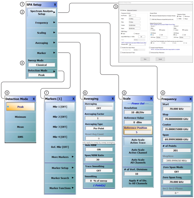
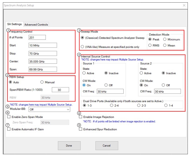
SPECTRUM ANALYSIS SETUP Dialog – SA Settings Tab - Classical Mode (1 of 2)
1. Frequency Control Pane.
2. RBW Setup Pane – Auto Mode.
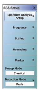
3. Sweep Mode Pane – Classical Mode.
4. Internal Source Control Pane.
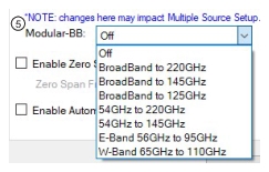
5. Modular-BB Drop-down.
6. Enable Zero Span Mode Checkbox.
7. Enable Automatic IF Gain Checkbox.
8. Enable Image Rejection Checkbox.
9. Enhanced Spur Reduction Checkbox.
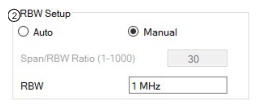
1. RBW Setup Pane – Manual Mode
2. Modular-BB Drop-down
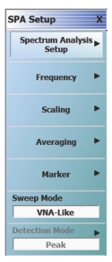
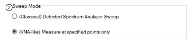
3. Sweep Mode Pane – VNA-like Mode
Frequency Control Pane
Allows set up of the receiver sweep parameters.
RBW Setup Pane
Allows setting of the resolution BW either in Auto mode established by a Span/RBW ratio or by manual entry of the RBW value. Note that from an instrument hardware perspective, RBW is the same as IFBW referred to elsewhere in the user interface.
Modular-BB Drop-down
Available on VNAs with Option 8x. Allows selection of BB/mmWave band.
Enable Zero Span Mode Checkbox
Selection will turn on Zero Span mode (equivalent to CW mode in the transmission/reflection and other applications). If enabled, the system will be set to measure at the user entered Zero Span frequency.
Enable Automatic IF Gain Checkbox
Selection will turn on Automatic IF Gain. This is off by default, as automatic gain decisions are based on signal amplitudes only directly at the IF. Recommended to be turned on only when an internal source is being used as a tracking signal.
Sweep Mode Pane
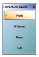
Allows selection of either the Classical or VNA-Like mode. If Classical sweep mode is enabled, selections for detection mode (Peak, minimum, RMS, mean) are displayed.
• Classical Mode: Like a typical spectrum analyzer, it measures at all frequencies between start and stop but will display at a user-specified number of points.
• VNA-Like Mode: Measures only at the points specified by the user. Very fast, for when the user knows where the signals of interest are.
Internal Source Control Pane
Allows setting of the internal source to the Active or Inactive state. Allows turning on of source CW mode at entered frequency.
Enable Image Rejection Checkbox
Selection will turn on Image Rejection. Number of sweep points will be limited when image rejection is enabled.
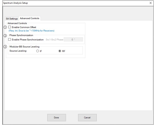
Enables Common Offset Mode. When Common Offset Mode is ON, both the LO and Source signals are referenced to a common oscillator.
When Common Offset Mode is OFF, the LO and Source signals are referenced to independent oscillators.
Enable Phase Synchronization Checkbox
Enables phase synchronization of the internal sources. When ON, the two internal sources can be programmed phase coherently (same phase relationship sweep to sweep) at the expense of a small increase in trace noise. Phase synchronization only has effect if both internal sources are set to Active.
Source Leveling Buttons
Allows selection of the internal source leveling path. RF implies the VNA detection on the RF drive path, while IF uses the test set detection on a reference IFs.
• Option 49 and Option 7 are installed on the VNA.
• The APPLICATION menu mode is set to Spectrum Analysis mode.
Navigation
• MAIN | Application | APPLICATION | Mode = Spectrum Analysis | Spectrum Analysis Setup | SPA SETUP | Frequency | FREQUENCY
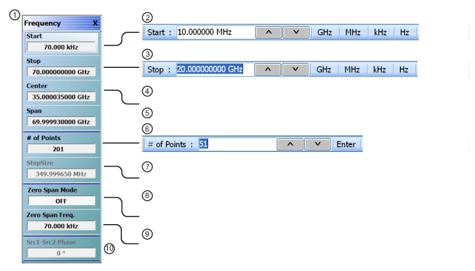
FREQUENCY Menu and Related Field Toolbars
1. FREQUENCY menu – Related button field toolbars shown to the right.
2. Start Frequency field toolbar.
3. Stop Frequency field toolbar.
4. Center Frequency field toolbar.
5. Span Frequency field toolbar.
6. # of Points field toolbar.
7. Step Size display-only button
8. Zero Span Mode button.
9. Zero Span Frequency field toolbar.
10. Src 1-Src 2 Phase field toolbar.
Start (Frequency)
Select displays the Start frequency field toolbar to provide input for the start frequency in GHz, MHz, kHz, or Hz.
Stop (Frequency)
Select displays the Stop frequency field toolbar to provide input for the stop frequency in GHz, MHz, kHz, or Hz.
Center (Frequency)
Select displays the Stop frequency field toolbar to provide input for the stop frequency in GHz, MHz, kHz, or Hz.
Span (Frequency)
Select displays the Span frequency field toolbar to provide input for the span frequency in GHz, MHz, kHz, or Hz.
# of Points
The Number of Points button displays the # of Points field toolbar and allows the user to enter the number of points for the frequency span, allowing separate parameter point settings for Zero Span Mode ON and Zero Span Mode OFF.
Step Size
A read-only field displays the calculated frequency step-size based on the requested frequency span and the number of points selected in the buttons above.
Zero Span Mode (Off/On)
Toggles Zero Span Mode OFF and ON.
Zero Span Frequency
Select displays the Zero Span Frequency field toolbar to provide input for the stop frequency in GHz, MHz, kHz, or Hz.
Src1-Src2 Phase
The Src1-Src2 Phase button is available when both internal sources are set to Active.
Select displays the Src1-Src2 Phase field toolbar and allows the user to set the required phase relationship between the two internal sources.
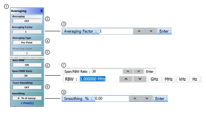
1. AVERAGING menu – Related button field toolbars shown to the right.
2. Averaging button.
3. Averaging Factor field toolbar.
4. Averaging Type button.
5. Reset Avg. Count button.
6. Auto RBW button.
7. Span/RBW field toolbar / RBW field toolbar.
8. Trace Smoothing button.
9. Smoothing field toolbar. Shows number of points below button.
Averaging (Off/On)
Button present for frequency-based and power-based sweeps. Select toggles averaging off and on.
Averaging Factor
Button present for frequency-based and power-based sweeps. Not present for segment-based sweeps. Select displays the Averaging Factor field toolbar.
Averaging Type (Per Point/Per Sweep)
Button present for frequency-based and power-based sweeps. Not present for segment-based sweeps. Select toggles between averaging per point and averaging per sweep.
Reset Avg. Count (Display only)
Button present for frequency-based, power-based, and segment-based sweeps. Read only display field. Counts up to the Averaging Factory value as the averaging session proceeds. Select resets the averaging count to 0 (zero), and the averaging session starts anew.
Auto RBW (Off/On)
Toggles auto RBW OFF and ON.
Span/RBW
Visible if Auto RBW is ON.
RBW
Visible if Auto RBW is OFF. Resolution bandwidth is akin to IFBW in the other applications.
Trace Smoothing (Off/On)
On a per-trace basis, toggles trace smoothing OFF and ON.
Smoothing
On a per-trace basis, select displays the Smoothing % field toolbar. The toolbar allows the user to set the percentage of trace smoothing in use. A display below the button field shows the number of points that are smoothed.
The measurement with the maximum linear magnitude of the measurements in the subrange of the given parameter will be displayed. This is the default selection.
Minimum
The measurement with the minimum linear magnitude of the measurements in the subrange of the given parameter will be displayed. This is useful for very dense signals in the sweep range of interest.
Mean
The arithmetic mean of the linear magnitudes of the given parameter will be used as the result for the subrange. This can also be useful for noise-like or stochastic signals or those that are otherwise very dense.
RMS
The root-mean-square value of the linear magnitudes of the given parameter will be used as the result for the subrange. This can be useful for noise-like signals.