Phase measurements are available in both S11 and S21 modes. 2-Port Phase measurements can use both High (approximately –7 dBm) and Low (approximately –40 dBm) power settings.
1-Port Phase Measurement
The following example compares the phase of two cables using a 1-port phase measurement. The dynamic range and phase uncertainty are better with 2-port phase measurements.
Procedure
1. Press the Measurement main menu key.
2. Press the More submenu key.
3. Press the 1-port Phase submenu key.
4. Set the Start Frequency and Stop Frequency or press Signal Standard to list the Signal Standard menu. If Signal Standard is pressed, determine the type of signal by pressing Uplink, Downlink, or Uplink plus Downlink. Then press the Select Standard submenu key to choose a signal from the Signal Standards List with the arrow keys or rotary knob and press Enter.
5. Press the Shiftkey, then the Calibrate(2) key and perform a 1-port calibration at the desired reference plane. See 1-Port Calibration Procedure (OSL).
6. Connect Cable A to the RF Out reference plane.
7. Press the Shiftkey, then the Trace(5) key.
8. Press the Copy Trace to Display Memory submenu key.
9. Remove Cable A and connect Cable B to the RF Out reference plane.
10. Press the Trace – Memory submenu key to view the difference in phase between the two cables.
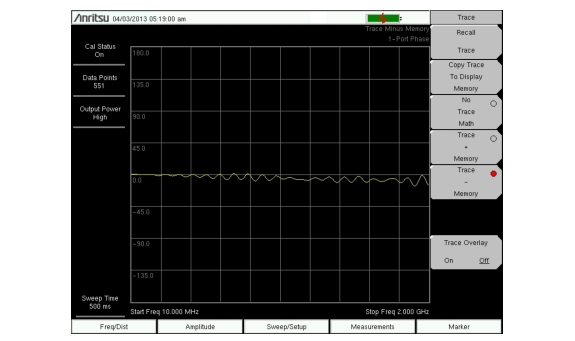
11. Figure: 1-Port Phase shows the difference in phase of cable A and cable B. The Trace Math menu is turned on and Trace A – Trace B is displayed.
1-Port Phase
2-Port Phase Measurement
The following example compares the phase of two cables using a 2-port phase measurement.
Procedure
1. Press the Measurement main menu key.
2. Press the More submenu key.
3. Press the 2-port Phase submenu key.
4. Set the Start Frequency and Stop Frequency or press Signal Standard to list the Signal Standard menu. If Signal Standard is pressed, determine the type of signal by pressing Uplink, Downlink, or Uplink plus Downlink. Then press the Select Standard submenu key to choose a signal from the Signal Standards List with the arrow keys or rotary knob and press Enter.
5. Press the Shiftkey, then the Calibrate(2) key and perform a 2-port calibration at the end of a phase stable cable. See 2-Port Calibration Procedure (OSLIT).
6. Connect Cable A (the reference cable) between the RF Out and RF In connectors.
7. Press the Shiftkey, then the Trace(5) key.
8. Press the Copy Trace to Display Memory submenu key.
9. Remove Cable A and connect Cable B (the cable under evaluation).
10. Press the Trace – Memory submenu key to view the difference in phase between the two cables.