Following is an example of configuring your Anritsu instrument for OBSAI testing on the uplink LTE signal (Port B Out from Port AB on the optical TAP). Your screen display and user menus may differ depending on your instrument model and firmware version.
1. If your test instrument is not in OBSAI measurement mode, press the front panel Menu key, then press the OBSAI RF application icon.
2. Press the Measurements main menu key at the bottom of the touch screen.
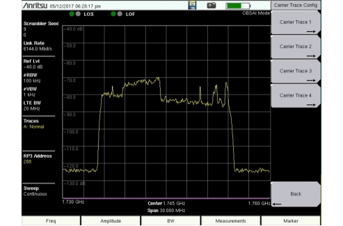
3. Before proceeding to the next step, verify that you have at least one active OBSAI link (LOS and LOF indicators above the trace window are both green). See Figure: Sample Spectrum Display.
4. Press Start OBSAI to initiate a scan of the OBSAI link for active RP3 addresses and detect the link rate. On dual-SFP instrument models, both links are scanned if active.
If no OBSAI carriers are found, a message indicating that the RP3 address list is empty will display when you attempt to configure a carrier trace in Step 6. Refer to RP3 Address.
5. If valid RP3 addresses are detected, the first address in the list is displayed as Carrier Trace 1 in a Spectrum view similar to Figure: Sample Spectrum Display. The display bandwidth is set to match the LTE bandwidth of Trace 1.
Sample Spectrum Display
6. Configure the display and remaining carrier traces as appropriate. Up to four traces can be displayed on a single display, or they may be distributed between the two displays in dual display mode. Refer to Carrier Trace Menu.
7. To change the view to Spectrogram, press the Measurements key, then Spectrogram.
Refer to the Spectrum Analyzer Measurement Guide for details on Spectrum Analyzer and Interference Analyzer (Spectrogram) functions.