The S820E can measure insertion loss of cables (or other 2‑port devices) using three different methods. If you have access to connect only one end of the cable to the instrument, then you must perform either One Port Testing using Cable Loss - One Port mode, or two port Transmission measurements using an external USB sensor.
For One Port Testing, the other end of the cable must be terminated in a short or open to provide a full reflection of the signal. This method provides accurate results when the cable loss is less than 10 dB.
When the cable loss values are higher than 10 dB, then the two‑port method must be used to obtain accurate results. If you are able to connect both ends of the cable to Port 1 and Port 2 of the Site Master (either directly or through a port extension cable), then you can use the 2‑port Transmission method. If you are able to connect only one end of the cable to the Site Master, then you can use the Transmission measurement with External Sensor.
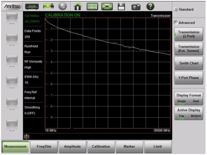
Press the Advanced submenu key to access the following measurements.
Transmission (2‑Port)
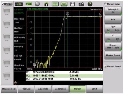
The S820E provides the capability to perform 2-port vector-corrected transmission measurements. These measurements are used to verify the performance of amplifiers and duplexers, as well as to verify antenna isolation. The excellent dynamic range also makes this measurement suitable for repeaters. When access is available to both ends of a cable or waveguide, the 2‑port transmission measurement provides the most accurate method to measure the attenuation in the cable or waveguide. Figure: 2‑Port Transmission Measurement Example, Waveguide is a 2‑Port transmission measurement example for a WR‑62 waveguide.
2‑Port Transmission Measurement Example, Waveguide
2‑Port Transmission Cable Loss Measurement Example
Transmission (Ext. Sensor)
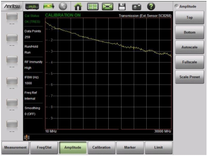
If you are able to connect only one end of the cable to the Site Master, then you can use the Transmission measurement with External Sensor. For this measurement, you connect the cable under test to Port 1 of the Site Master, and you connect a USB transmission sensor or power sensor to the other end of the cable. USB extenders can be used for long cable runs. This measurement provides accurate results of cable loss up to 30 dB. This is a scalar measurement, providing only magnitude data (no phase) and, therefore, does not use vector error correction for its calibration steps. Instead, it uses a sensor reference calibration. Figure: External Sensor Transmission Measurement Example is a Cable Loss Measurement Example of an External Sensor Transmission.
External Sensor Transmission Measurement Example
When performing both transmission and return loss measurements on the same cable, for best results, the return loss should be measured with a good‑quality termination at the end of the cable.
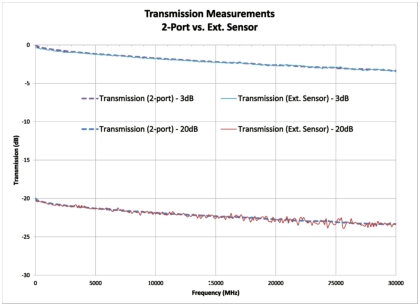
Figure: Transmission Measurements Compared shows a comparison between measurements made using both 2‑Port and External Scalar Transmission methods. The 2‑Port Transmission measurement will always produce the most accurate results. Even with 20 dB of loss, however, the External Sensor Transmission measurement produces results that are comparable, as shown in the figure.
Transmission Measurements Compared
Note
The external USB sensors that are supported by the S820E for transmission measurements are the SC8268 Transmission Sensor and the USB power sensors that are listed in the S820E Technical Data Sheet.
Smith Chart
The Smith Chart is a graphical tool for plotting impedance data versus frequency. It converts the measured reflection coefficient data into impedance data and displays it in a manner that makes the Smith Chart a useful tool for determining and tuning input match. This complex impedance plot reveals which matching elements (capacitance, inductance) are necessary to match a device under test to the reference impedance (which can be set to either 50 ohms or 75 ohms). Markers can be used to read the real and imaginary parts of the complex impedance.
1‑Port Phase
The S820E can display the phase of the reflection measurements at Port 1. The Phase display range is from –450 degrees to +450 degrees.
The 1‑port phase measurement is most useful when making relative measurements (comparing the phase of one device to the phase of another) by utilizing the Trace Math function (Trace – Memory).