S820E Microwave Site Master™ User Guide : Cable and Antenna Measurements
 
Cable and Antenna Measurements
 
Introduction
Standard Measurements
Return Loss or VSWR Measurement
Cable Loss Measurement
Distance‑To‑Fault (DTF)
Using DTF Aid
Transmission Line Selection
Distance Resolution
Windowing
DMax (Maximum Usable Distance)
DTF Measurement Examples
Advanced Measurements
Transmission Measurements
Transmission (2‑Port)
Transmission (Ext. Sensor)
Smith Chart
1‑Port Phase
Measurement Setup
Frequency
Distance
Amplitude
Sweep
Limit Lines
Markers
Trace
Cable and Antenna Analyzer Menus
Measurement Menu
Freq/Dist Menu
Freq/Dist Menu (Continued)
Windowing Menu
Amplitude Menu
Calibration Menu
Marker Menu
Marker Menu (Continued)
Limit Menu
Limit State Menu
Limit Menu (Continued)
Sweep Menu
Sweep Trigger Menu
Trace Menu
Other Menus Keys
Introduction
This chapter provides an overview of Cable and Antenna measurements and how to set up the instrument and perform basic line sweeps.
Note 
Use the Menu key and confirm that the instrument is in Cable‑Antenna Analyzer Advanced mode (not Classic mode). In Classic mode, Classic Mode is clearly displayed at the top of the instrument screen in the System Function Tool Bar.
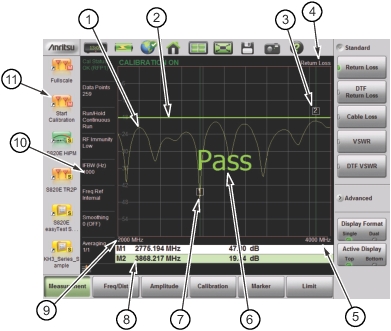
Figure: Cable and Antenna Display Overview illustrates a typical Cable and Antenna Return Loss measurement.
Note 
Screen images in this User Guide are illustrations of typical instrument features. Some images may include instruments other than the Site Master S820E. Traces and other display features may differ from the screen displays of your instrument.
 
Cable and Antenna Display Overview 
1.  
Active Trace (Yellow)
2.  
Limit Line (Green when Passing)
3.  
Marker 2 (Marker to Peak)
4.  
Measurement Type
5.  
Stop Frequency (F2)
6.  
Pass Message (Active trace is below the limit line in Return Loss measurement)
7.  
Marker 1 (Marker to Valley)
8.  
Marker Table
9.  
Start Frequency
10.  
Measurement Details (also Menu Shortcuts)
11.  
User‑defined Setup and Menu Shortcuts (not available in Classic mode)