 | |
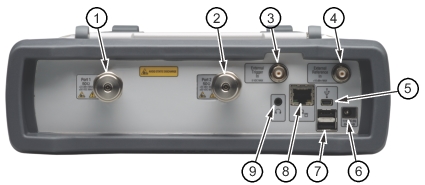
1. | Port 1, Type N, Female (Options 0708, 0714) or Ruggedized K, Male (Options 0720, 0730, 0740) 50 ohm impedance. Maximum input is +23 dBm at ±50 VDC. Torque to 12 lbf·in or 1.4 N·m (N connector) or to 8 lbf·in or 0.90 N·m (K connector). |
2. | Port 2, Type N, Female (Options 0708, 0714) or Ruggedized K, Male (Options 0720, 0730, 0740) 50 ohm impedance. Maximum input is +23 dBm at ±50 VDC. Torque to 12 lbf·in or 1.4 N·m (N connector) or to 8 lbf·in or 0.90 N·m (K connector). |
3. | External Trigger In, Type BNC(f), 50 ohm A sweep is triggered on the rising edge of a TTL signal. Maximum input is +5 VDC. |
4. | External Reference In, Type BNC(f), 50 ohm Auto‑detects a 10 MHz external reference. When active the Measurement Setting for Freq Ref displays “External”. Maximum input is +10 dBm. |
5. | USB Interface – Type Mini‑B (version 2.0) The USB 2.0 Mini‑B connector can be used to connect the Site Master directly to a PC. |
6. | External Power, 5.5 mm Barrel Connector The external power connector is used to power the instrument and for battery charging. Input is 11 VDC to 14 VDC at up to 4.0 A. When using the AC‑DC Adapter, always use a grounded three‑wire power cable that is connected to a three‑wire power line outlet. Failure to use properly grounded electrical equipment may result in severe or potentially fatal injury. |
7. | USB Interface – Type A (version 2.0) The Site Master has two Type A USB 2.0 connectors that accept USB Flash Memory devices for storing or transferring measurements, setups, and screen shots. USB sensors that are used for 2‑port cable loss measurements and high accuracy power meter measurements and certain USB peripheral devices (such as a USB GPS module, USB mouse, or USB keyboard) may also be supported. |
8. | RJ45 connector (10/100 Ethernet) Used to connect the Site Master to a local area network. When the instrument is connected to a network, the instrument obtains an IP address via DHCP, or a static IP address can be set by the user. Refer to Status Menu for information about obtaining the IP address of the instrument. |
9. | Headset Jack The jack accepts a 3.5 mm 3‑wire miniature phone plug such as those commonly used with cellular telephones. The speaker output is diverted to the headphone when the headphone is plugged into this jack. |