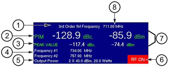
In this example of the PIM Summary Table, the instantaneous PIM values (item
2) are displayed with white numerals, indicating that these values are below the upper limit value that was set for this measurement. The peak PIM values (item
3) are also displayed with white numerals, indicating that those values are within the upper limit value setting. If the measurement trace exceeds the upper limit line setting at any time during a measurement, then the peak values are displayed in red and remain red after the measurement is completed. The instantaneous PIM values (item
2) are displayed with red numerals only while the measurement exceeds the limit.
The RF ON indicator (item
6) is displayed in the PIM Summary Table only while the measurement is in progress, that is, while RF is being transmitted. The Test submenu key, in which the word Measure is underlined while the measurement is in progress, is also highlighted in red while RF is present.
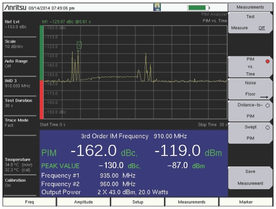
Note the PIM bar graph at the left edge of the sweep window. In this graph, the instantaneous PIM level is displayed in units of dBc by the red bar on the vertical axis. No limit was set for this particular measurement.
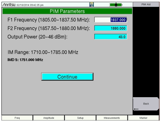
The PIM Parameters dialog box (
Figure: PIM Parameters Dialog Box) displays when you press the
PIM Aid submenu key, which is available by pressing the
Freq main menu key or the
Setup main menu key. This dialog box displays the current carrier frequencies, power, and intermodulation product generated by the selected carrier frequencies. In addition, frequencies for F1 and F2 and the carrier power can be changed in this dialog box. Use the
Arrow keys or the touch screen to scroll through the three settings (F1, F2, and Power). The chosen value changes color to indicate when the value is ready for editing. Then use the number keypad to enter a value, which must be within the range that is indicated on the screen. After editing the value, you must press the
Enter key or the appropriate submenu key (
MHz for frequency or
Enter for power). The highlighting changes to indicate that the new value has been set. When all three settings are satisfactory, scroll to highlight the
Continue button and press the
Enter key, or use the touch screen to press the
Continue button, or press the
Back submenu key. To abort a setting, before pressing
Enter or the
MHz submenu key or the
Enter submenu key, press the
Esc key or an
Arrow key, which allows you to enter a different value. Pressing the
Esc key when no setting is pending returns the display to the previous menu. To abort a setting, before pressing
Enter or the
MHz submenu key or the
Enter submenu key, touch the
Continue button, which returns to the same previous menu as when pressing the
Back submenu key.