During calibration, RF power is present, and the red RF On light is illuminated.
Calibrations are temperature‑dependent. A temperature deviation of approximately 20 degrees Celsius voids an existing calibration. Two temperatures are displayed in a white font (in all PIM measurement modes) in the Instrument Settings Summary, just above the Calibration On/Off message. One is the temperature in the PIM Master now, and the other is the temperature in the PIM Master at calibration. When the current temperature (labeled now) changes up or down to within 2 degrees of the calibration limit, the font color of the current temperature is displayed in yellow. This color changes to red if the current temperature exceeds the calibration limit. N/A is displayed for the calibration temperature when no valid calibration file exists for the current instrument settings.
All calibrations are valid for an initial 12‑hour limit. If the PIM Master remains On, and if all settings remain consistent, then the current calibration file remains effective. If any setting is changed after 12 hours, including a power cycle of the PIM Master (Off and On), then a warning is presented indicating that the current calibration is more than 12 hours old. The message instructs the user to verify the instrument residual PIM level and re-calibrate if necessary. Calibrations can be used again after settings are changed and then returned to the previous settings for which the calibration was performed.
The standard calibration calibrates Distance-to-PIM, Swept PIM, PIM vs. TIME, and Noise Floor - Time View for the current instrument settings. A user-defined-calibration dialog is available allowing users to select specific calibrations they wish to perform, and this allows multiple power level calibrations to be performed at the same time (refer to Other Calibrations Menu).
If you are performing a Noise Floor Spectrum View measurement, a separate calibration is required. Press the Start Cal Spectrum View button in the Noise Floor menu, and then follow the on‑screen instructions to calibrate the Spectrum View. (Alternately, you can use the User Defined Calibration Dialog Box.)
Note
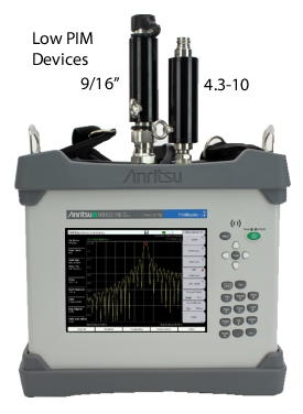
Consult the technical data sheet for part numbers used in calibration.
1-Port Calibration
Procedure
The following steps describe the standard calibration process.
1. Press Shift then Cal (2).
2. In the Calibration menu, press the Start Calibration submenu key.
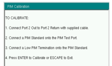
3. If conducting a high-band intermodulation measurement (i.e., PCS, 1900 MHz, or IM2), ensure the PIM Master receiver port is open (disconnected) and skip to Step 4. For all other bands, connect the appropriate PIM standard onto the test port of the PIM Master or at the end of the PIM test cable.
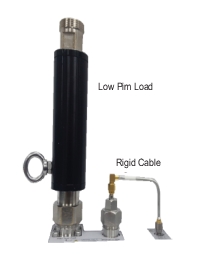
4. Connect an appropriate Low PIM Load onto the PIM output port or to the Low PIM standard if used.
5. Press Enter to calibrate or Esc to exit.
6. If you are conducting a high band intermodulation measurement as noted in Step 3, skip to Step 13. During the calibration, CALIBRATION IN PROCESS... is displayed on the measurement screen in red letters, and a beep is emitted when this step is completed.
7. When prompted, remove the PIM standard and the Low PIM Load and then connect only the Low PIM Load.
8. Press Enter to calibrate or Esc to exit.
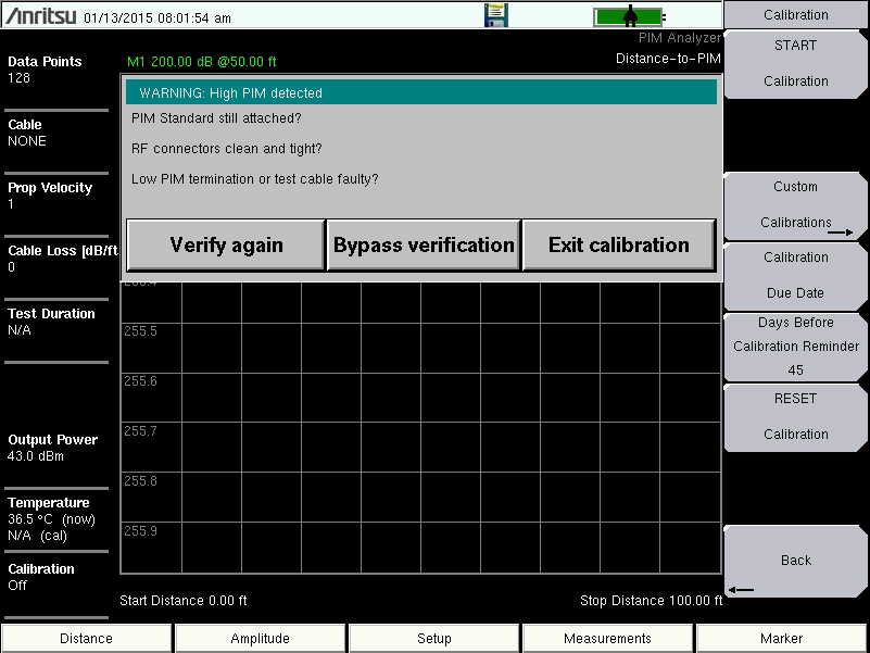
9. If the Low PIM Load is better than –88 dBm, then the calibration continues, as in Step 10. If the Low PIM Load just installed has high PIM, then this calibration will not be useful. If the measured PIM is worse than –88 dBm, then a warning is displayed. See Figure: Bad Load Detection (High PIM) Warning. The displayed warning provides 3 options.
a. Verify again After you have made corrections, press this button to continue the calibration.
b. Bypass verification Press this button to ignore the warning and continue the calibration.
c. Exit calibration Press the button to abort the current calibration.
10. During the calibration, CALIBRATION IN PROCESS... is displayed on the measurement screen in red letters, and a beep is emitted when this step is completed.
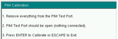
11. When prompted, remove all components from the test port leaving nothing connected at the point of calibration (Open circuit).
12. Press Enter to calibrate or Esc to exit.
13. During the calibration, CALIBRATION IN PROCESS... is displayed on the measurement screen in red letters. When calibration is complete, two beeps are emitted, and Calibration On is displayed at the bottom of the Instrument Settings Summary.
Bad Load Detection Feature
The second part of a calibration requires removal of the PIM Standard and reattachment of the Low PIM Load. If the Low PIM Load has measured PIM worse than –88 dBm, then the WARNING: High PIM detected dialog box is displayed (as shown in Figure: Bad Load Detection (High PIM) Warning).
Bad Load Detection (High PIM) Warning
1-Port Residual PIM Verification
For the 2-port residual PIM procedure, see 2-Port Residual PIM Verification. Perform this test immediately following a calibration or when instructed to do so, such as when 12 hours or more have elapsed since the existing calibration was performed. Attach the Low PIM Load to the Test Port or to the end of the PIM test cable.
Note
Confirm that all the connectors are clean of debris or contamination that may cause incorrect PIM measurement results.
Set to Factory Preset
1. PIM measurement results.
2. Power on the PIM Master.
3. Press the Shift key and then the Mode (9) key.
4. Use the Up/Down arrow keys to highlight PIM Analyzer, and then press the Enter key to switch to PIM Analyzer mode.
5. Press the Shift key and then the Preset (1) key.
6. Press the Preset submenu key to set the instrument to the factory preset state.
Verify Residual PIM
1. From the Measurements menu, press the PIM vs. Time submenu key.
2. Press the Test submenu key so that Measure is underlined.
3. Lightly tap on the Low PIM Load and flex the PIM test cable (if attached) during the PIM vs. Time test. The peak PIM value should be at least 10 dB below the pass/fail criteria for the DUT.
If the measured PIM is outside of the limit in Step 3, then you may have one of the following problems:
• Metal flakes inside one or more RF connectors
• Loose RF connector
• Faulty Low PIM Load
• Worn connector saver
• Damaged PIM Test Port connector
Investigate and repair the source of any problem, and then repeat the calibration process.
Verifying the PIM Standard
1. Connect a PIM Standard to the Test Port or to the end of the PIM test cable.
2. Connect a Low PIM Load to the PIM Standard.
3. From the Measurements Menu, press the PIM vs. Time submenu key, followed by the Test submenu key so that Measure is underlined.
• Measurements > Swept PIM > Frequency > 2-Port Mode
Note
Two-port mode may be entered only when Band Select is set to Low.
2. Press Shift then Cal (2).
3. In the Calibration menu, press the Start Calibration submenu key.
The PIM Master displays the to PIM Calibration prompt.
PIM Calibration Start Prompt
4. Follow its steps:
a. Connect Port 2 Out to Port 2 Return with supplied cable.
b. Connect a PIM Standard device on to the PIM Test Port.
c. Connect a Low PIM Load device (p/n 2000-1749-R) onto the PIM standard device.
2-Port Calibration Set Up-Phase 1
d. When all the torque values have been confirmed, press Enter to start calibration.
5. When the calibration completes, the instrument shows the this prompt.
PIM Calibration Start Prompt
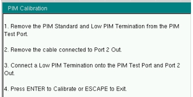
6. Follow its steps:
a. Remove the PIM standard device and the Low PIM Load device from the PIM Test Port.
b. Remove the cable from Port 2 Out and from Port 2 Return.
c. Connect one Low PIM Load device to each of PIM Test Port and Port 2 Out.
2-Port Calibration Set Up
d. When all the torque values have been confirmed, press Enter.
7. When this phase of the calibration completes, the PIM Master displays this prompt.
PIM Calibration Finish Prompt
8. Follow its steps:
a. Remove the load devices from the PIM Test Port and Port 2 Out.
b. Leave the PIM Test Port open.
c. Press Enter to complete the calibration.
9. After the third phase of the calibration is finished, depending upon the test mode (PIM v Time, PIM Distance, or Swept PIM) the last phase performs an actual test.
The test will take as long as long as the value in Setup > Test Duration submenu.
2-Port Residual PIM Verification
For the1-Port residual PIM procedure, see 1-Port Residual PIM Verification. Perform this test immediately following a calibration or when instructed to do so, such as when 12 hours or more have elapsed since the existing calibration was performed. Attach the Low PIM Load to the Test Port or to the end of the PIM test cable.
Note
Confirm that all the connectors are clean of debris or contamination that may cause incorrect PIM measurement results.
Set to Factory Preset
1. PIM measurement results.
2. Power on the PIM Master.
3. Press the Shift key and then the Mode (9) key.
4. Use the Up/Down arrow keys to highlight PIM Analyzer, and then press the Enter key to switch to PIM Analyzer mode.
5. Press the Shift key and then the Preset (1) key.
6. Press the Preset submenu key to set the instrument to the factory preset state.
Verify Residual PIM
1. Press Freq main menu key.
2. Press 2-Port Low Band mode to ON.
3. Press Shift key and then CAL (2) Key.
4. Press Start Cal submenu key. Follow the on screen instructions until completion of the calibration.
5. Press Measurement main menu then select Swept PIM mode.
6. Leave the two test ports terminated with Low PIM Loads.
7. Press the Measurements main menu key.
8. Press the Test submenu key to initiate the test. The key has Measure underlined and goes red when the test is in progress.
9. Verify the measurement result that is displayed on the PIM Master instrument is < –123 dBm with output power 2 x 43 dBm.
10. Press the Setup main menu key and select High output power.
1For option 703, the upper band is available only in 1-port mode.
Note
Typical values are shown. PIM Standards can vary ± 3 dB due to manufacturing variation. Record the starting value of your PIM Standard, and use that value for test equipment verification.