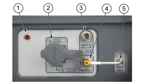
PIM Master™ Passive Intermodulation Analyzer with Site Master™ Cable & Antenna Analyzer (331) and 2-Port Options (703) User Guide : PIM Master Overview : Top Connector Panel -- Option 703
 
Top Connector Panel -- Option 703
The 2-port top connector panel includes the base features from Figure: PIM Master Top Panel Layout plus those for the 2-port.
PIM Master Top Panel Layout: 2-Port
1.  
Indicator Light for RF On (Red)
2.  
PIM Test Connector, 7/16 DIN, female, 50 Ω
3.  
VNA RF Out Connector, Type‑N, female, 50 Ω (Option 331)
4.  
Port 2 Out Connector, 4.3-10, female, 50 Ω (Option 703)
5.  
Port 2 Return Connector, Type SMA, female, 50 Ω (Option 703)
6.  
Strap Bracket (not shown), 2x
Port 2 Out Connector (item 4 in Figure: PIM Master Top Panel Layout: 2-Port)
VNA RF Out Connector, 4.3-10, female, 50 ohms (Option 703). This test port is available only on instruments with 2-Port LTE Option 703. It is used to perform Return Loss, VSWR, Cable Loss, and Distance‑to‑Fault (DTF) measurements. Hand tighten this connection. Do not use a wrench.
Port 2 Return Connector (item 5 in Figure: PIM Master Top Panel Layout: 2-Port)
Port 2 Return Connector, SMA, female, 50 ohms (Option 703). This test port is available only on instruments with 2-Port LTE Option 703. Hand tighten this connection. Do not use a wrench.
Note 
Use care to use all wrenches in such a way that the rigid cable is not impacted.