Limit lines are used for visual reference or for pass/fail criteria using the limit alarm and pass/fail message settings. Pressing either the Limit (6) key or the Limit main menu key displays the Limit menu.
Overview of limit lines:
• Each measurement has a unique limit line.
• The color of the limit line changes to red when a measurement trace exceeds a limit.
• Limits set beyond the current amplitude range are displayed at either the top or bottom of the graticule.
• The limit line amplitude is stored when a limit line is turned off.
• Limit Preset will turn off the limit line display, limit alarm and Pass/Fail message, and reset upper and lower limits to their default values.
Limit Line Functions
1. Press Limit (6), then press the Active Limit key (if necessary) to choose Upper or Lower.
2. Press the Limit State key, then press Single or Segmented to turn on a measurement‑specific limit line.
A single limit line extends over the entire displayed range of the sweep, independent of the start/stop settings of the sweep. For a single limit line, the amplitude for the start/stop points is the same. A segmented limit line can be divided into connected or disconnected segments with different start/stop x and y values.
Note
Both the upper and lower limit lines for a trace must be of the same type, either single or segmented.
3. Press Move Active Limit and use the virtual keypad to enter an amplitude value in the edit box.
4. Press the dB key or Enter to apply the new power level and close the edit box.
Note
Limit lines cannot be moved by using the touch screen on your tablet.
5. For segmented limit lines, press Edit Segments to display the Segments menu. A table displays active limit line segments.
6. Tap on a limit line segment, then choose to Add, Edit, or Delete the segment. For editing purposes, consider a single, full‑span limit line as a single segment. Press the Close submenu key or the ESC key to close the Segments submenu and return to the Limit menu.
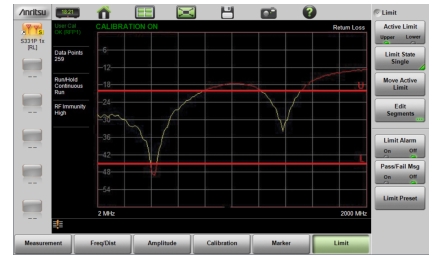
Upper limit lines and segments are labeled with a “U”, and Lower lines and segments are labeled with an “L”. Limit lines are displayed in green so long as the limits are not reached or exceeded. When a limit is exceeded (upper or lower), the limit line or segment turns red (Figure: Limit Lines and Trace Showing Fail Colors). Any portion of the measurement trace touching or exceeding a limit also turns red, while portions of the trace within limits remain in the default yellow color. When Segmented Limits are used, the trace color does not change if the limits are exceeded.
Limit Lines and Trace Showing Fail Colors
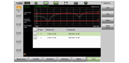
When editing a segmented limit line, a table is displayed with each segment in a separate row (Figure: Table of Limit Lines (or Segments)). The type is displayed as U or L. The Start and Stop settings are displayed as Start(x1,y1) and Stop(x2,y2). In a Return Loss measurement, for example, the x‑axis is in units of frequency, and the y‑axis is in units of dB.
Table of Limit Lines (or Segments)
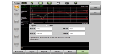
When adding or editing a segmented limit line, a dialog box (Figure: Segment Editing Dialog Box) provides setting choices. You can choose Upper or Lower, then enter the x‑axis and y‑axis values for the segment Start and Stop. Differing y‑axis values result in a sloping line segment.
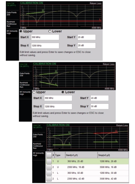
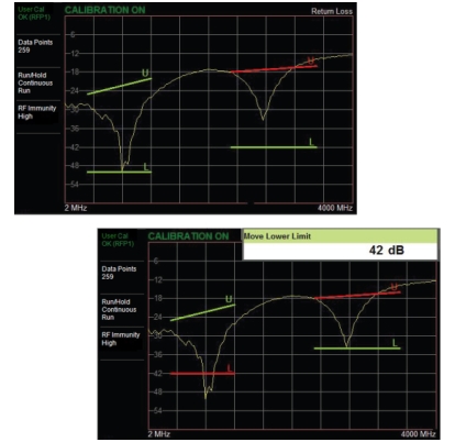
Figure: Moving Limit Line Segments shows the result of moving limit line segments. Note that when moving upper or lower segments, all segments of the same type will be moved by the same amplitude value, meaning all upper or lower segments will move simultaneously. To change the value of a single segment, use the Edit Segments function.
Moving Limit Line Segments
Limit Alarm
Press the Limit Alarm key under the Limit menu to turn on or off the audible Limit Alarm at the tablet or PC. Audio controls are set via the controller device.
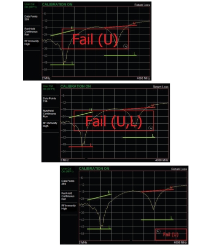
Pass/Fail Messages
When set to On, a Pass or Fail message is displayed. Fail is displayed when the trace crosses or touches a limit line, as illustrated in Figure: Pass/Fail Message Turned On. Note that Upper (U) or Lower (L) or both (U, L) are displayed. To change the size and location of the Pass/Fail message, tap the small circled arrow in the lower‑right corner of the large format message box. The circled arrow is in the upper-left corner when the message is in small format.