 |
|
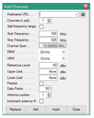
Parameter | Description |
Host name/URL | Enter a host name or URL address for the instrument taking measurements. If using the simulator program, enter 127.0.0.1 for the Hostname. |
Channels to add | Will add to the Table List the number of channels designated in the entry box. Type in a value using the number keypad or the up/down arrow buttons to increment/decrement the number of desired channels. |
Split frequency range | The frequency span is split into the sub-channels. For example: Start Frequency is set at 600 MHz and Stop Frequency set at 700 MHz with 10 channels to add. • If Split Frequency Range is not checked, 10 channels set at 600 MHz to 700 MHz. • If Split Frequency Range is checked, 10 channels each with a 10 MHz span. 600 MHz to 610 MHz, 610 MHz-620 MHz, etc. |
Start Frequency | Type in the desired start frequency using the number keypad. The maximum frequency setting Vision provides is the maximum allowed on the measuring instruments up to 54 GHz. |
Stop Frequency | Type in the desired stop frequency using the number keypad. The maximum frequency setting Vision provides is the maximum allowed on the measuring instruments up to 54 GHz. |
Channel Span | Channel Span displays the individual channel spans when Split Frequency Range is checked. So in the Split frequency range example above, it will be blank if Split Frequencies is not checked, and show 10 MHz if Split Frequencies is checked. |
RBW | Type or enter a RBW value from the list. The selectable range is 10 Hz, 30 Hz, 100 Hz, 300 Hz, 1 kHz, 3 kHz, 10 kHz, 30 kHz, 100 kHz, 300 kHz, 1 MHz, 3 MHz. |
VBW | Type or enter a VBW value from the list. The selectable range is 10 Hz, 30 Hz, 100 Hz, 300 Hz, 1 kHz, 3 kHz, 10 kHz, 30 kHz, 100 kHz, 300 kHz, 1 MHz, 3 MHz. |
Reference Level | Type in the desired start power range using the number keypad. The entry range is –120 to 20 dBm. |
Upper Limit | Type in the desired upper limit using the number keypad. The entry range is –120 to 20 dBm. |
Lower Limit | Type in the desired lower limit using the number keypad. The entry range is –120 to 20 dBm. |
Preamp | Select this box to use the preamp. Checked will activate the preamp to reduce noise. |
Data Points | Type in the desired data points using the number keypad. |
Antenna number | Type in a value using the number keypad or the up/down arrow buttons to increment/decrement the number of antennas. The selectable range is 1 to 24. |
Increment Antenna # | If checked, the antenna number starts at 1 and will increment for each channel added. For example, if five channels are added, the antenna number will start at 1 and increment to 5. If not checked, the antenna number will always be 1. |
Replace | Replace entire Table List with current Add Channel configuration. |
Add | Include the Add Channel configuration to the bottom of Table List. |
Insert | Click a channel number before opening the Add Channel dialog. Click Insert to add the Add Channel configuration above the selected channel number. This allows the user to insert at the top of the Table List. |
Close | Close the Add Channels dialog. |