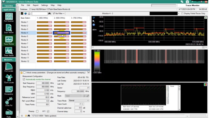
To set up a PoA locate measurement, select a channel from the Trace Monitor window as shown in Figure: Monitor #4 Selected.
Monitor #4 Selected
Monitored Area
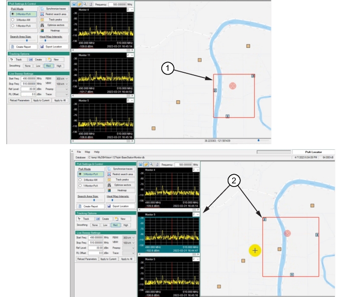
Refer to Figure: Change PoA Monitor. The selected Spectrum Analyzer from Trace Monitor is displayed on the screen as Spectrum Analyzer “1” on the PoA map. As default, the closest two Spectrum Analyzers are shown and labeled as Spectrum Analyzer “2” and Spectrum Analyzer “3”. These are the three Spectrum Analyzers initially set to measure the interferer signal. The three Spectrum Analyzers are enclosed in a red-boundary capture range rectangle used to calculate the interferer location.
Up to three Spectrum Analyzers can be selected in the Trace Monitor menu. The red-boundary measurement window encloses the three Spectrum Analyzers selected.
Change Measurement Monitors on PoA Map
Click another probe on the PoA map or click a trace display repositions the red-boundary to include the selected Spectrum Analyzer. The number of probes displayed on the PoA map can be changed using Application Settings Window and then add Spectrum Analyzers using the set the Maximum Number of Probes, Note that only three can be set to make interferer measurements.
Change PoA Monitor
1. Initial PoA Measurement
2. Clicked Monitor / Changed Boundary
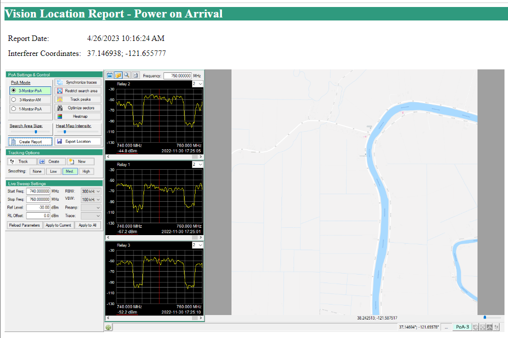
PoA Report
The report generated is shown in Figure: PoA Report. The report includes a screenshot of the PoA screen, Report Date, and the Interferer Coordinates. The report can be printed and saved in a user designated folder.