The MS2090A Field Master Pro uses two connector panels to provide for all physical IO. These panels use a variety of connector types intended for their purpose.
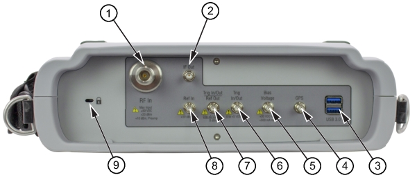
RF Connectors
The main RF input connector is Type N, Type K, or Type V, depending on the frequency option that is installed. These are 50 Ω connectors. Type N connectors are female and Type K and V are male. Additional IO is provided with the SMA style connectors. The SMA connectors are 50 Ω female.
Note
Versions of the Field Master Pro that were manufactured before November 2021 featured SMB style connectors, which are 50 Ω slip-on connectors. Port functionality is the same with either connector.
Caution
To prevent damage to your instrument, do not use pliers or a plain wrench to tighten the connectors. Do not overtighten the connector. The recommended torque for Type K and V is 8 lbf·in (0.9 N·m or 90 N·cm). The recommended torque for Type N is 12 lbf·in (1.35 N·m or 135 N·cm).
Maximum Input: ±50 VDC, +23 dBm, +13 dBm with Preamp On
To prevent damage to your instrument, do not try to mate incorrect connector types or use pliers or a plain wrench to tighten the connector. Do not overtighten the connector. The recommended torque for Type K and V is 8 lbf·in (0.9 N·m or 90 N·cm). The recommended torque for Type N is 12 lbf·in (1.35 N·m or 135 N·cm).
2. IF Out
This 50 Ω SMA connector provides internal IF output. The nominal frequency range is 325 MHz with FFT capture bandwidth ≤ 32 MHz and 300 MHz with FFT capture bandwidth = 100 MHz. The nominal RF output level is –4 dBm with a 10 MHz, –20 dBm input, and with 0 dB input attenuation and preamp off. The spectrum can be inverted in certain RF input bands. Refer to spectrum analyzer measurement guide (10580-00447) for information about Zero Span IF Output (Option 89). To prevent damage to your instrument, do not use pliers or a wrench to tighten the connector.
3. USB Interface – Type A
The Field Master Pro has three Type A and one Type C USB connectors that accept USB storage devices for saving measurements, setup data, and screen images. Two connectors are located on the top panel and one is located on the side panel. To ensure the device or its data does not become corrupted, select the eject icon to eject (unmount) the USB device before it is unplugged from the USB port (see Title bar).
Note
The MS2090A is compatible with external USB memory devices that have an integrated keypad and are FIPS compliant using AES 256-bit encryption.
4. GPS Antenna Connector
The GPS port on the Field Master Pro is a 50 Ω female SMA connector. This connector also provides 5.0/3.3 VDC for an active GPS antenna. To prevent damage to your instrument, do not use pliers or a wrench to tighten the connector.
5. Bias Voltage
The bias voltage output port is a 50 Ω SMA connector. The power supply is set up to provide 1 V to 34 V with a resolution of 0.1 V. The maximum current is 1 A, but with at total maximum power of 15 W. To prevent damage to your instrument, do not use pliers or a wrench to tighten the connector.
6. Trigger In/Out
A TTL signal that is applied to the external trigger 50 Ω SMA input connector causes a single sweep to occur. In spectrum analysis, triggering is generally used in zero span, and triggering occurs on the rising edge of the signal. After the sweep is complete, the resultant trace is displayed until the next trigger signal arrives. To prevent damage to your instrument, do not use pliers or a wrench to tighten the connector.
7. Trigger In/Out / Ref Out (10 MHz)
This port can be configured as a trigger in/out as above or as a reference output. The reference output port is a 50 Ω SMA connector that provides 10 MHz at approximately –7 dBm to 0 dBm. To prevent damage to your instrument, do not use pliers or a wrench to tighten the connector.
8. Ref In
The external reference input port is a 50 Ω SMA connector that provides for input of an external frequency reference. Refer to your Technical Data Sheet for valid frequencies. The instrument automatically selects the frequency reference in the following order of priority: external, GNSS (GPS), then the internal time base. To prevent damage to your instrument, do not use pliers or a wrench to tighten the connector.
9. Kensington® Lock (K-slot)
Provides a slot that accepts Kensington style cable locks.
The MS2090A is compatible with external USB memory devices that have an integrated keypad and are FIPS compliant using AES 256-bit encryption.
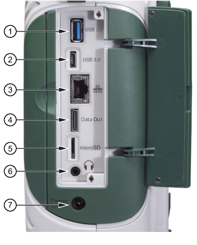
1. USB Interface – Type A
The Field Master Pro has three Type A USB connectors that accept USB storage devices for saving measurements, setup data, and screen images. Two connectors are located on the top panel and one more is located on the side panel. To ensure the device or its data does not become corrupted, touch the eject icon to eject (unmount) the USB memory device before it is unplugged from the USB port (see Title bar).
2. USB Interface – Type C
The USB Type-C port is used to connect the Field Master Pro directly to a PC and provides a remote SCPI programming interface via USBTMC (USB Test and Measurement Class). Refer to the MS2090A programming manual for remote SCPI control setup and command.
3. LAN Connection
The RJ‑45 connector is used to connect the Field Master Pro to a local area network or directly to a PC with an Ethernet crossover cable. See Ethernet Connection for more details.
4. Data Out Port
The Data Out port is used for IQ Streaming. Refer to IQ Capture/Streaming measurement guide (10580-00490) for more information. This is a multi-purpose, hot pluggable input/output (I/O) interface.
5. MicroSD
The Micro Secure Digital slot is a small expansion slot located on the side panel. The slot accepts industry standard MicroSD storage cards and can be used for storing measurements, setup data, and screen images similar to USB storage devices.
Note
The MicroSD slot is currently not supported.
6. Headset Jack
The 3‑wire headset jack provides audio output from the built‑in sounds generated by the instrument. The jack accepts a 3.5 mm 3‑wire miniature phone plug such as those commonly used with cellular telephones.
7. External Power
This is a 2.5 mm by 5.5 mm barrel connector, 15 VDC, 5 A, center positive. The external power connector is used to power the unit and for battery charging. An orange blinking LED power button indicates that the instrument battery is being charged by the external charging unit. The indicator is a steady green when the battery is fully charged.
Warning
When using the AC-DC Adapter, always use a three-wire power cable that is connected to a three-wire power line outlet. If power is supplied without grounding the equipment in this manner, the user is at risk of receiving a severe or fatal electric shock.