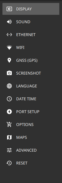
The DISPLAY settings allow you to adjust the display brightness, choose the display color scheme and to view or hide shortcuts to the saved application settings.
Brightness
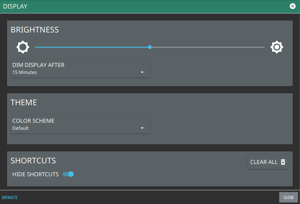
The BRIGHTNESS option consists of a slider to adjust the screen brightness, in addition to selecting the amount of idle time before the screen automatically dims to conserve battery life.
The DIM DISPLAY AFTER drop-down provides up to 15 minutes idle time settings. Or you can select NEVER option to keep the display illuminated for as long as the instrument remains powered on.
Note that DIM DISPLAY AFTER feature will only work if the instrument is running on the battery. This feature will not work if the unit is connected to the AC power supply.
Display Settings
Theme
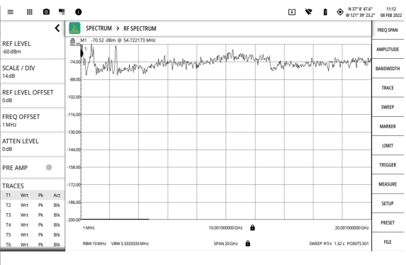
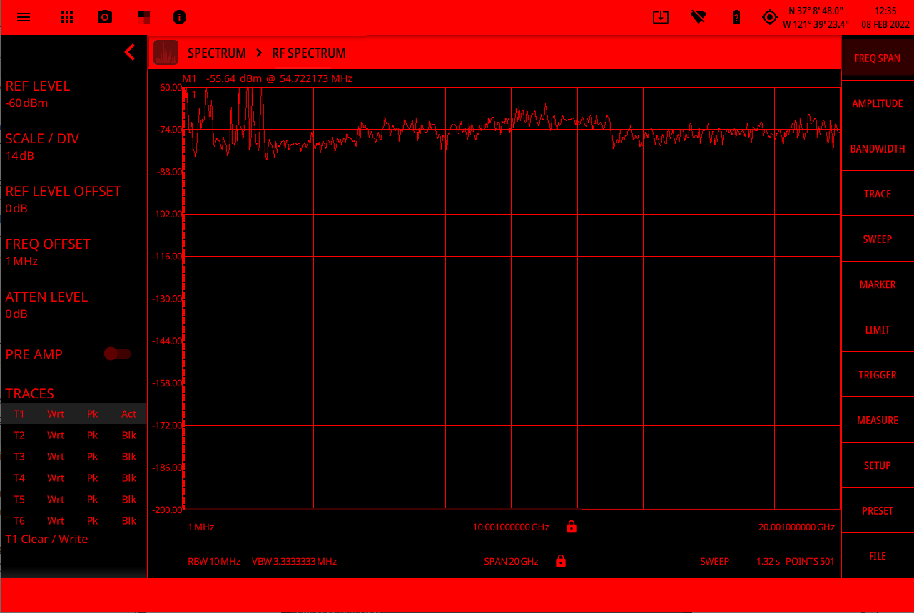
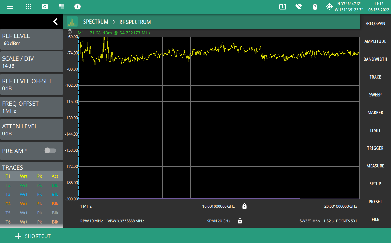
Under THEME option select COLOR SCHEME drop-down menu and select either Default, Light, Black on White or Night Vision to set the display color scheme of your choice. If the THEME is set to Light it may be more suitable for viewing in bright ambient conditions. But if the THEME is set to Night Vision it may be suitable for viewing in a poorly lit night time conditions.
Light Theme Display
Black on White Theme Display
Night Vision Theme Display
Shortcuts
Under the SHORTCUTS option, toggle the HIDE SHORTCUTS button to view or hide the shortcuts.
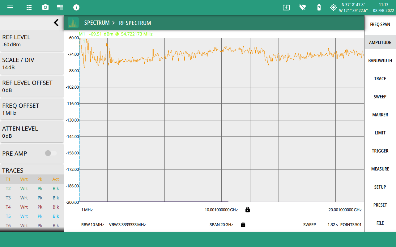
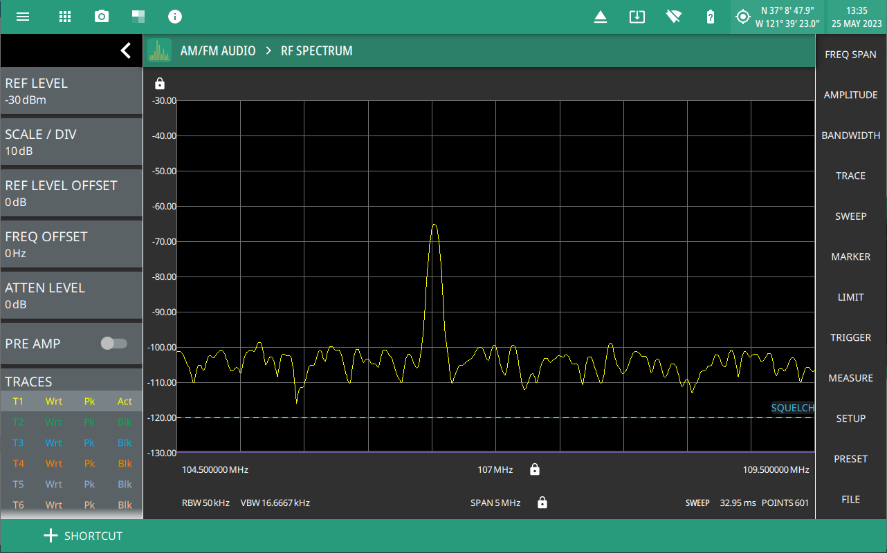
Select + SHORTCUT button located at the bottom left of the display screen to create or save specific settings of an application.
Shortcut Button
Follow the steps below to create/load/rename a shortcut:
1. Select +SHORTCUT button at the bottom left of the instrument display screen.
+Shortcut button
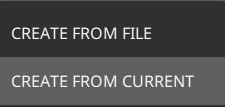
2. Select CREATE FROM FILE option to create a new shortcut from an already saved setup file.
3. Otherwise, select CREATE FROM CURRENT option to create a shortcut of the current (trace) settings of the instrument.
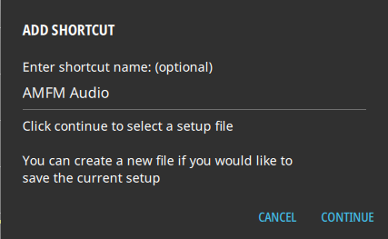
4. Enter the shortcut name which is optional, and select CONTINUE.
Add Shortcut Dialog
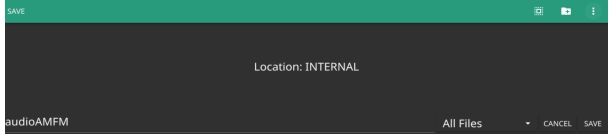
5. Enter a file name to save the current setup, and select SAVE.
File Save As
6. Select the newly created shortcut to recall the saved setup file.
To delete all the shortcuts, select SYSTEM MENU (3-line icon), go to SETTINGS menu, select DISPLAY settings and select CLEAR ALL button at the bottom right of the instrument’s display.
Recalled Setup File: Shortcut Button
Sound Settings
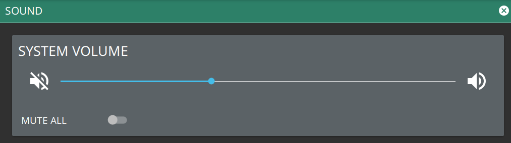
The SOUND settings allow you to adjust the SYSTEM VOLUME or MUTE ALL of the instrument sounds. The system volume may affect other volume settings found in various setup menus.
Sound Settings
Network Settings
The MS2090A uses Ethernet or WLAN (Wi-Fi) to communicate remotely with a controller. Most instrument functions (except power on/off) can be controlled via a network connection to a PC connected directly (with an Ethernet cross‑over cable or Wi-Fi peer-to-peer) or through a network. The instrument software supports the TCP/IP raw socket network protocol.
Ethernet networking uses a bus or star topology in which all of the interfacing devices are connected to a central cable called the bus, or are connected to a hub. Ethernet uses Carrier Sense Multiple Access/Collision Detection (CSMA/CD) access method to handle simultaneous transmissions over the bus. This standard enables network devices to detect simultaneous data channel usage, called a collision, and provides for a contention protocol. When a network device detects a collision, the CSMA/CD standard dictates that the data is retransmitted after waiting a random amount of time. If a second collision is detected, the data is again retransmitted after waiting twice as long. This is known as exponential back off.
Wi-Fi uses a similar star topology in which all of the interfacing devices are connected to an access point. Wi-Fi uses Carrier Sense Multiple Access/Collision Avoidance (CSMA/CA) access method to handle simultaneous transmissions. CSMA/CA doesn’t detect collisions but rather avoids them through the use of a control message. If the control message collides with another control message from another node, it means that the medium is not available for transmission and the back-off algorithm is applied before attempting another transmission.
The TCP/IP setup requires the following:
• IP Address: Every computer and electronic device in a TCP/IP network requires an IP address. An IPv4 address has four numbers (each between 0 and 255) separated by periods. For example: 128.111.122.42 is a valid IP address.
• Subnet Mask: The subnet mask distinguishes the portion of the IP address that is the network ID from the portion that is the station ID. The subnet mask 255.255.0.0, when applied to the IP address given above, would identify the network ID as 128.111 and the station ID as 122.42. All stations in the same local area network should have the same network ID, but different station IDs.
• Default Gateway: A TCP/IP network can have a gateway to communicate beyond the LAN identified by the network ID. A gateway is a computer or electronic device that is connected to two different networks and can move TCP/IP data from one network to the other. A single LAN that is not connected to another LAN requires a default gateway setting of 0.0.0.0. If you have a gateway, then the default gateway would be set to the appropriate value of your gateway.
• Ethernet Address: An Ethernet address, or Media Access Control (MAC) address, is a unique 48‑bit value that identifies a network interface card to the rest of the network. Every network card has a unique Ethernet address permanently stored in its memory.
• Remote programming and operation between the instrument and remote program is accomplished via a TCP/IP raw socket connection to port 9001. The remote program must establish a TCP/IP raw socket connection at port 9001 to the MS2090A.
• The remote program may connect to the instrument IP address or to its HOSTNAME (Ethernet only). If using DHCP instead of a static IP, using the HOSTNAME may be more reliable for finding an instrument on a network.
• The instrument supports multicast DNS (mDNS). This allows a client that also supports mDNS to connect to the instrument using its hostname without needing to setup a local name server. To use mDNS add the .local top-level domain to the instrument hostname. For example, if the instrument’s hostname is "AnritsuInstrument", an mDNS client could access the instrument with "AnritsuInstrument.local".
• You may need to contact your network administrator to ensure network security policies, anti-virus, and firewall settings do not block access to the controlling computer and its ports.
The MS2090A can be configured for Dynamic Host Configuration Protocol (DHCP), an Internet protocol that automates the process of setting IP addresses for devices that use TCP/IP, and is the most common method of configuring a device for network use.
To determine if a network is set up for DHCP, connect the instrument to the network and select DHCP protocol. Power cycle the instrument. If the network is set up for DHCP, the assigned IP address should be displayed in the network settings.
Ethernet Connection
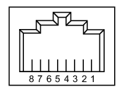
Interface between the instrument and other devices on the network is via a category five (CAT‑5) interface cable connected to a network. This cable uses four twisted pairs of insulated copper wires terminated into an RJ45 connector. CAT‑5 cabling is capable of supporting frequencies up to 100 MHz and data transfer speeds up to 1 Gbps, which accommodates 1000Base‑T, 100Base‑T, and 10Base‑T networks. CAT‑5 cables are based on the EIA/TIA 568 Commercial Building Telecommunications Wiring Standard developed by the Electronics Industries Association. A pinout diagram is shown in Table: 8‑pin Ethernet RJ45 Connector Pinout Diagram.
8‑pin Ethernet RJ45 Connector Pinout Diagram
Pin
Name
Description
Wire Color
1
TX+
Transmit data (> +3 volts)
White/Orange
2
TX–
Transmit data (< –3 volts)
Orange
3
RX+
Receive data (> +3 volts)
White/Green
4
–
Not used (common termination)
Blue
5
–
Not used (common termination)
White/Blue
6
RX–
Receive data (< –3 volts)
Green
7
–
Not used (common termination)
White/Brown
8
–
Not used (common termination)
Brown
Integrated into the RJ45 connector are two LEDs that illuminate as follows:
• LED 1 Off: 10 Mbit/s LAN connection
• LED 1 Orange: 100 Mbit/s LAN connection
• LED 1 Green: 1000 Mbit/s LAN connection
• LED 2 Amber/Yellow: On or blinking indicates LAN traffic
The instrument IP address and its HOSTNAME are set via the System menu (upper left corner) and accessing the ETHERNET or WIFI settings menu.
Note
Wi-Fi does not support connections using HOSTNAME; use IP addressing to establish a wireless network connection.
TCP/IP connectivity requires setting up the parameters described at the beginning of this section. The following is a brief overview of how to set up a general LAN connection on the MS2090A.
Note
You may need to consult your network documentation or network administrator for assistance in configuring your network setup.
Ethernet Settings
Refer to Network Settings for general network setup and information.
1. Access the System menu (3-line icon in the upper left corner).
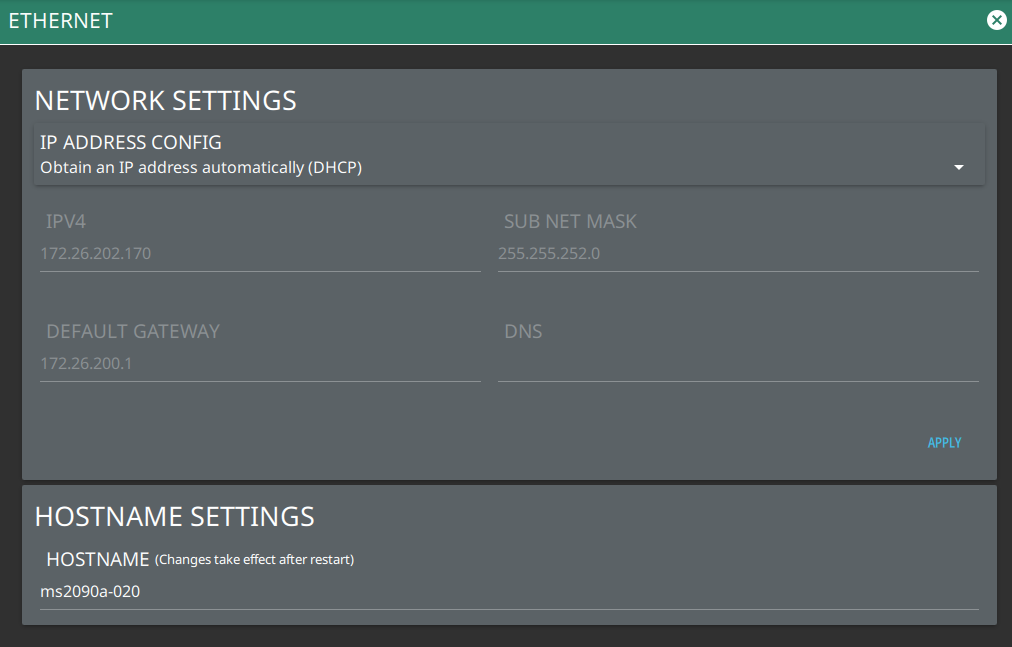
2. Select SETTINGS to access the instrument settings menu, then select ETHERNET to view the current network settings (IP address, HOSTNAME, etc.).
Ethernet Settings
The instrument IP address can be set automatically using DHCP or manually by entering the desired IP address, gateway address, and subnet mask.
Note
If an active Ethernet cable is connected to the instrument while it is turned on, a reboot may be required to establish a DHCP connection. If the port becomes inactive, verify that an active Ethernet cable is attached to the instrument, then cycle the instrument power off and on.
WiFi Settings
Refer to Network Settings for general network setup and information.
1. Access the System menu (3-line icon in the upper left corner).
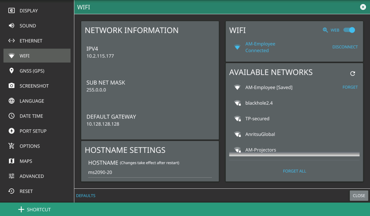
2. Select SETTINGS to access the instrument settings menu, then select WIFI to display the current network settings (IP address, HOSTNAME, etc.).
Wi-Fi Settings
The instrument IP, subnet mask, and gateway address are managed by the access point or wireless router.
Note
An active Wi-Fi connection to an access point must be established in order to enable DHCP.
If Wi-Fi becomes inactive, cycle the instrument power off and on, then verify that the Wi-Fi device is connected to an access point.
Field Master Pro is not able to connect to networks that require sign-in through web servers.
3. Enable the Wi-Fi radio by toggling it on from the right-side panel, then select an access point from the list.
4. When an access point is selected, the keyboard will display for you to enter the access point key (or password).
5. The access point will display below the toggle as the active connection.
6. Select WEB button to navigate to WEB to access the Internet. Refer to WEB for more information.
GNSS (GPS) Settings (Option 31)
The MS2090A Field Master Pro is available with a built-in global positioning receiver feature (Option 31) that can provide latitude, longitude, altitude, and UTC timing information. This option also enhances frequency reference oscillator accuracy. When the global positioning receiver is actively locked to satellites, this information is saved with all saved measurements.
Note
The MS2090A Field Master Pro Data Sheet provides a list of the options and measurements that require GNSS Receiver (Option 31). In addition to having Option 31 installed, a GPS antenna is required. Refer to the instrument Technical Data Sheet for compatible GPS antennas.
The MS2090A supports the following global positioning satellite systems:
• GPS: The United States Global Positioning System (GPS). GPS is currently the world's most utilized satellite navigation system.
• GNSS: Global Navigation Satellite System, a term used worldwide. This term includes the combinations of GPS, GLONASS, BeiDou and Galileo. Accessing multiple satellites provides increased accuracy, redundancy, and availability at all times.
Activating the GNSS (GPS) Feature
Attach the GPS antenna to the GPS connector on the top of the instrument and follow the steps below:
1. Access the SYSTEM menu (3-line icon in the upper left corner).
2. Select SETTINGS to access the instrument settings menu, then select GNSS (GPS) to open the GNSS (GPS) settings window.
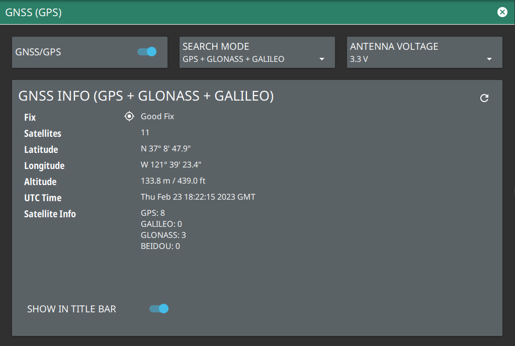
GNSS (GPS) Settings
3. Activate the GNSS (GPS) by sliding the GNSS/GPS toggle button to on.
4. Select SEARCH MODE button to select the combination of the satellite systems.
5. Set ANTENNA VOLTAGE to 3.3 or 5.0 V.
6. When the GNSS (GPS) receiver has established a “good fix”, the GNSS (GPS) icon is displayed with a center dot and the following information is kept updated:
• Fix status
• Tracked satellites
• Latitude
• Longitude
• Altitude
• UTC timing information
• Satellite Info
7. Toggling SHOW IN TITLE BAR shows the GNSS (GPS) coordinates in the Title bar at the top of the display.
After GNSS (GPS) location fix is attained, the internal reference oscillator begins to correct its frequency to match the GNSS (GPS) standard. After the internal frequency is adjusted to match the GNSS (GPS) standard, the status is indicated by GPS High Accuracy showing in the Status panel, which is displayed on the left side of the measurement display. When the GNSS (GPS) feature is not enabled, the reference source displays either “Internal Standard Accuracy” or a user‑selected external reference frequency in the Status panel.
In order to acquire data from the GNSS (GPS) satellites, you must have line‑of‑sight to the satellites, or the antenna must be placed outside with no obstructions. If no GNSS (GPS) is connected for at least three days, the Frequency Reference annotation reads Int Std Accy.
Screenshot
1. Access the System menu (3-line icon in the upper left corner).
2. Select SETTINGS to access the instrument settings menu, then select SCREENSHOT to open the screenshot setup menu.
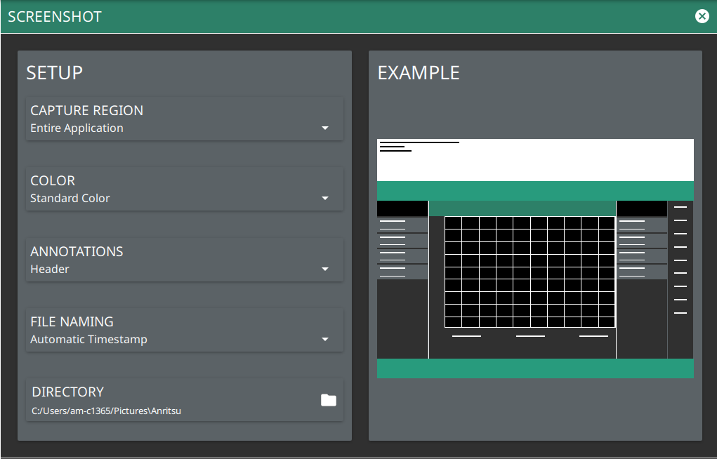
Screenshot Setup
Screenshot setup lets you configure the following:
• CAPTURE REGION: Captures entire window or graph area only.
• COLOR: Standard or printer-friendly.
• ANNOTATIONS: May be placed at top (header), bottom (footer) of captured image, or can be excluded (none).
• FILE NAMING: Saves a file with an automatic or manual time stamp.
• DIRECTORY: Directory path to destination folder where the file is to be saved.
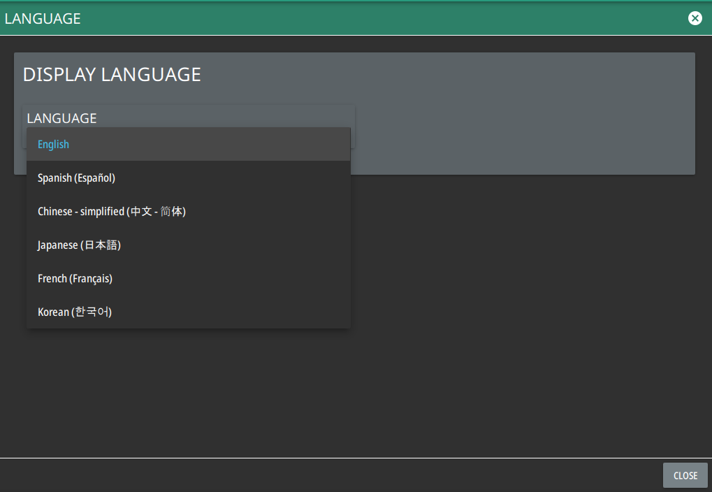
Follow the steps below to access language settings in order to change a selected display language:
1. Access the System menu (3-line icon in the upper left corner).
2. Select SETTINGS to access the instrument settings menu, then select LANGUAGE to open the language menu.
Note
If you select a different language, the primary menus and the screen annotation gets updated, but the keyboard used for file naming and similar tasks, notification messages and specific system menu names remain in the English language.
Language Settings
3. Select the LANGUAGE drop-down menu and select a desired display language as shown in the Figure: Language Settings.
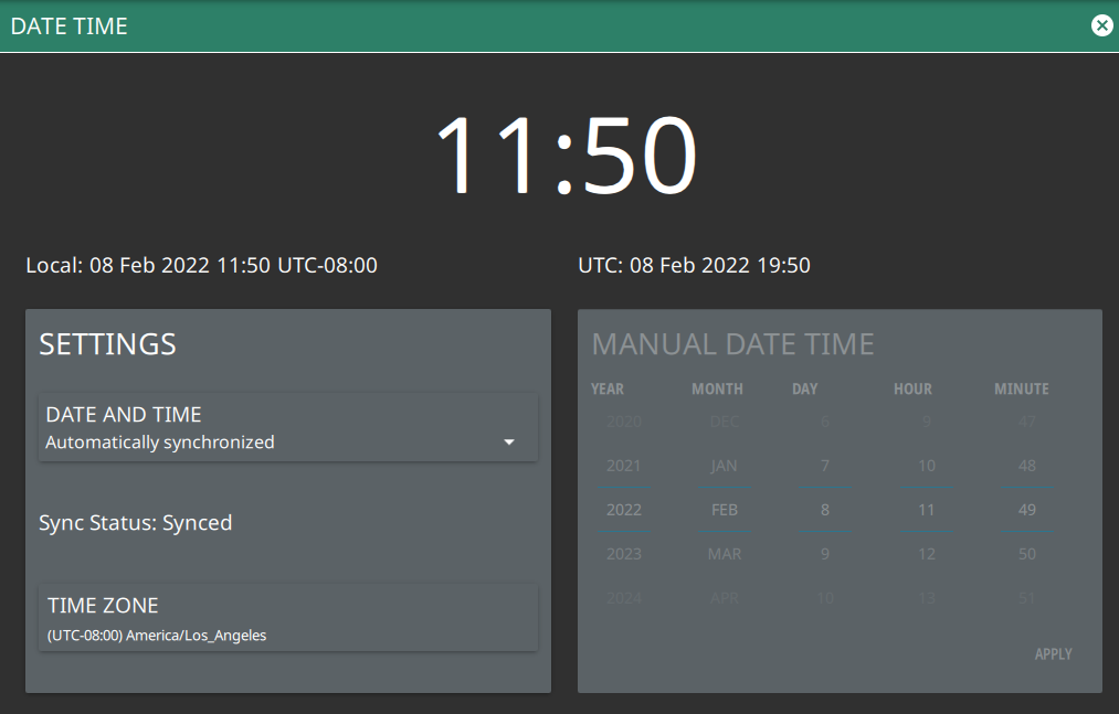
Date Time Settings
1. Access the System menu (3-line icon in the upper left corner).
2. Select SETTINGS to access the instrument settings menu, then select DATE TIME to display the current date and time settings.
Date Time Settings
The Date Time setup lets you set the current date and time and the time zone.
• Date and Time: Manually set or automatically synchronized. When synchronized (Sync Status: Synced), the system uses the network time; if the instrument also has a GNSS (GPS) location fix, the system will determine and use the more accurate of the two, between network and GNSS (GPS) time. Select Manually set to activate the MANUAL DATE TIME window. Here you can scroll to a selectable year, month, day, hour, and minute.
• Time Zone: Lists the selectable time zones.
Port Setup
The Port Setup menu allows you to configure the external ports.
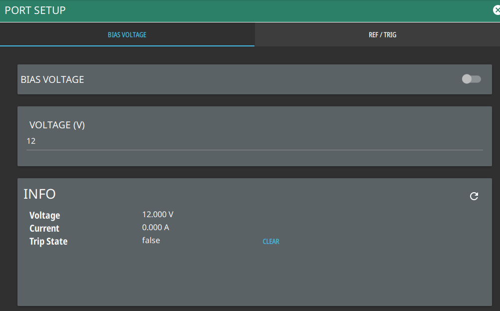
Bias Voltage
Bias Voltage setup provides controls to set the voltage level and to monitor the precise voltage and current, and trip state.
1. Access the System menu (3-line icon in the upper left corner).
2. Select SETTINGS to access the instrument settings menu, then select PORT SETUP to display the top panel bias voltage output settings.
Bias Voltage Port Settings
3. Manually set the voltage in the range of 0 V to 34 V (note: stable output voltage setting is ≥ +1 V).
4. Toggle the bias voltage on or off.
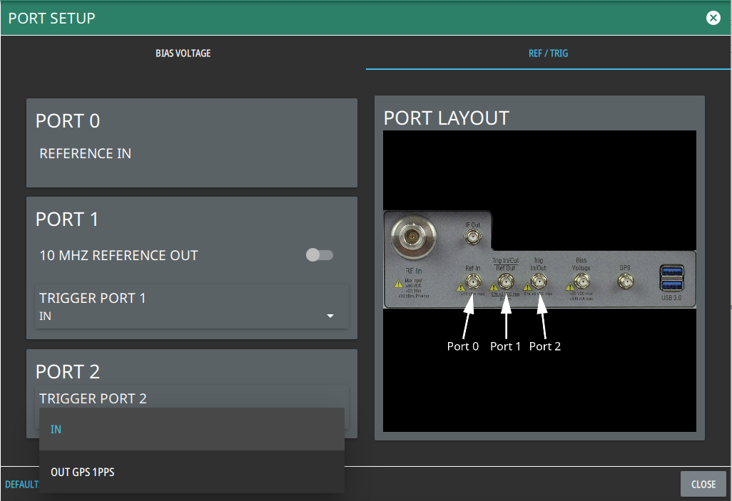
Reference and Trigger
The reference and trigger setup provides controls to set the functionality of the configurable top panel reference and trigger ports.
1. Access the System menu (3-line icon in the upper left corner).
2. Select SETTINGS to access the instrument settings menu, then select PORT SETUP > REF / TRIG to display the top panel reference and trigger port settings.
Reference/Trigger Port Settings
Note
PORT 0 is always a reference in port.
3. To set PORT 1 as a reference output, toggle 10 MHz REFERENCE OUT on. Otherwise, PORT 1 can be selected as a trigger input or trigger output by using the drop-down selection.
4. Use the drop-down selections to select PORT 2 as a trigger input or trigger output (GPS 1 PPS).
Options Settings
To view the installed and available options, follow the steps below:
1. Access the System menu (3-line icon in the upper left corner).
2. Navigate to SETTINGS to access the instrument settings menu.
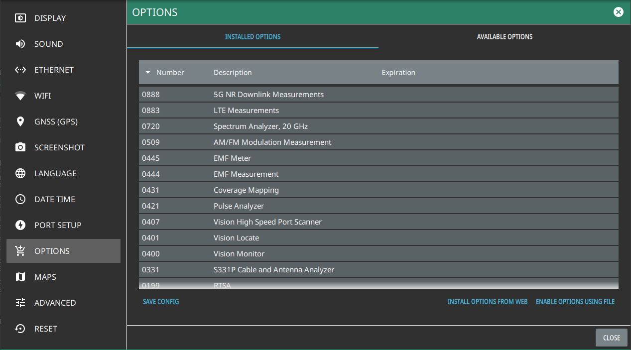
3. Select OPTIONS to view the list of currently installed options in the left tab, and available options in the right tab. Time-limited options will show the expiration date in the EXPIRATION column.
4. Some options can be installed using only a software file. Others may require additional hardware. Contact your local sales or service representative for information on ordering or installing new options. Refer to Upgrading Software Options for more information.
Note
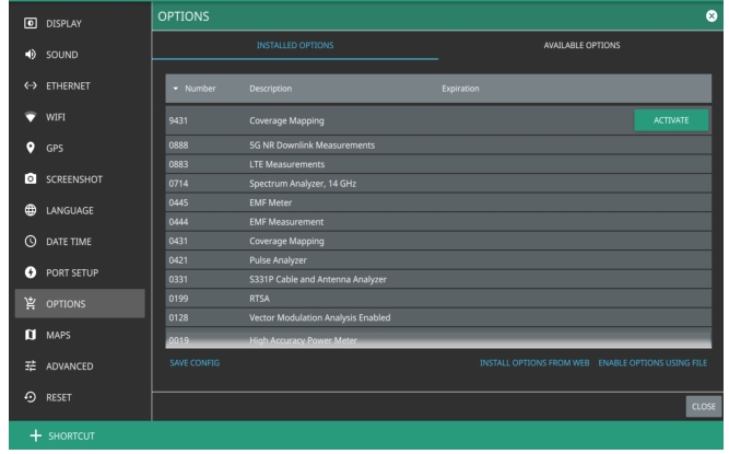
Not all instrument models offer every option. For example, Coverage Mapping Option (0431) is offered as a 90-day time limited option by ordering Option 9431. The option start time begins when the user first activates the option. Please refer to the Technical Data Sheet of your instrument for information on purchasing limited options
5. To upgrade your instrument with a specifically purchased option, select INSTALL OPTIONS FROM WEB to install options available on the web. Ensure that the unit is connected to the Internet.
6. Select ENABLE OPTIONS USING FILE to install options file saved in USB memory device.
7. Select SAVE CONFIG to export the config file to Anritsu.
Options Settings
Caution
Once a time limited option is activated, the 90-day time period begins countdown and cannot be halted. Ensure you intend to activate the option before selecting Activate.
To activate the installed time-limited options select the ACTIVATE button to begin the 90-day trial.
Options Settings
Maps Settings (Option 431)
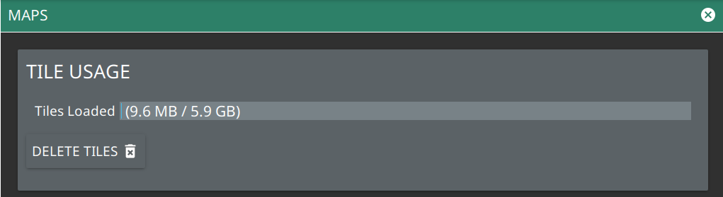
Map settings are available when Option 431, Coverage Mapping is installed. Maps settings are used to delete map tiles from instrument memory. Refer to Coverage Mapping section in spectrum analyzer measurement guide (10580-00447).
1. Access the System menu (3-line icon in the upper left corner).
2. Select SETTINGS to access the instrument settings menu.
3. Select MAPS to display the maps tile usage.
4. To free up internal storage space, delete loaded tiles using the DELETE TILES button. All tiles will be deleted.
Maps Settings (Option 431)
ADVANCED
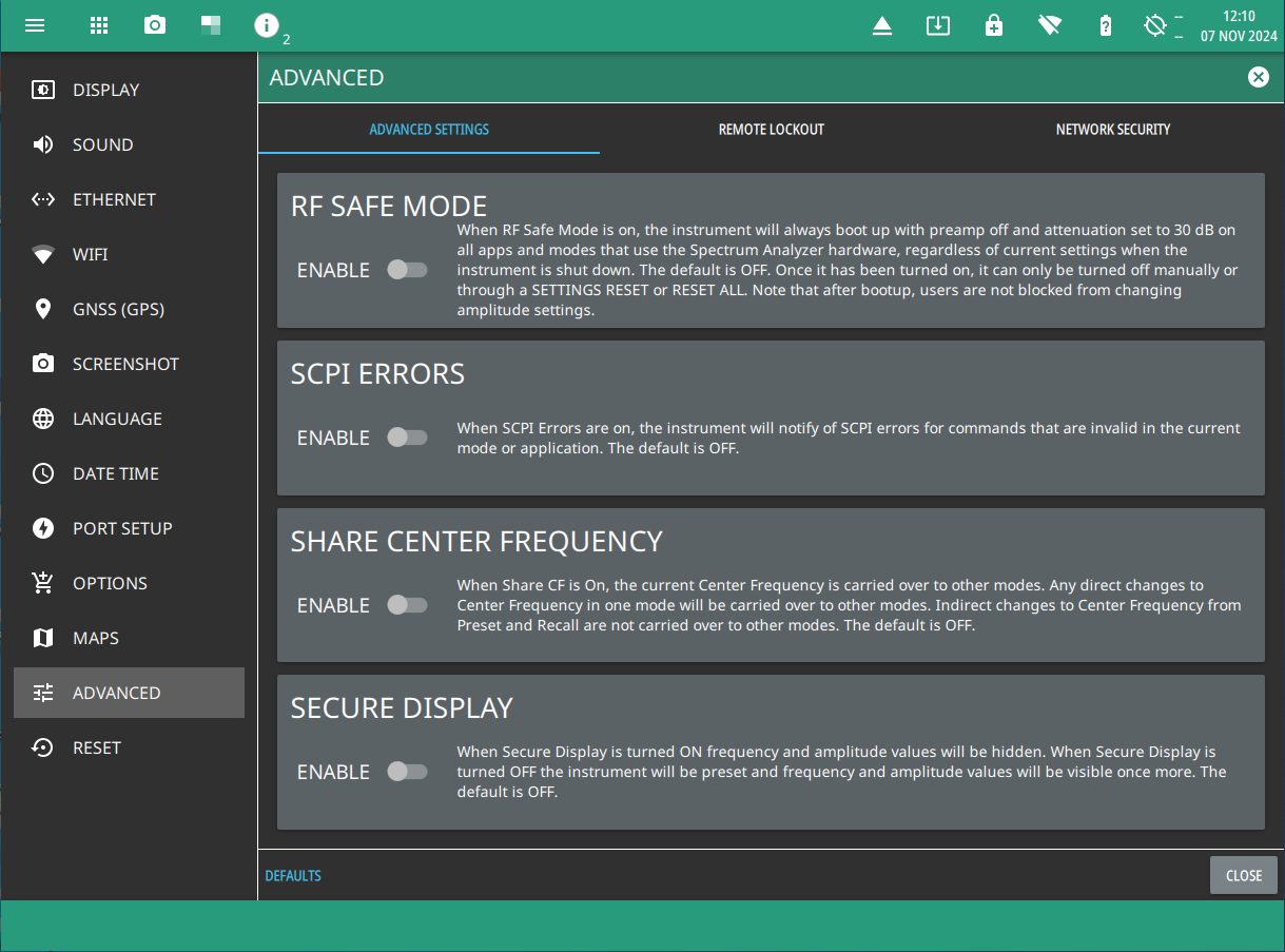
ADVANCED menu consists of ADVANCED SETTINGS, REMOTE LOCKOUT and NETWORK SECURITY tabs.
Advanced settings tab can be accessed
1. Access the System menu (3-line icon in the upper left corner).
2. Select SETTINGS to access the instrument settings menu.
3. Select ADVANCED to access ADVANCED SETTINGS, REMOTE LOCKOUT AND NETWORK SECURITY tabs.
Advanced Settings
ADVANCED SETTINGS
Use advanced settings tab to enable/disable the following options:
• Toggle RF SAFE MODE on to protect the internal detection circuitry on boot-up.
• Toggle SCPI ERRORS on to get notified of the errors in the invalid SCPI commands.
• Toggle SHARE CENTER FREQUENCY on to maintain the changes in center frequency set directly in one mode consistent across all the modes. Note that any indirect changes via preset and recall are not carried over.
• Turn on SECURE DISPLAY toggle to enable secure data blanking. The frequency and amplitude values will be hidden and replaced with ‘#’ symbols. Note that frequency and amplitude values will be blanked in markers and limits. Refer to Secure Data (Option 7) for detailed information.
Note
SHARE CENTER FREQUENCY section is disabled in CAAUSB and HIPM applications.
Note
SECURE DISPLAY toggle is only available in SPA and CAAUSB applications. Secure display section is not included in instruments without Option 7.
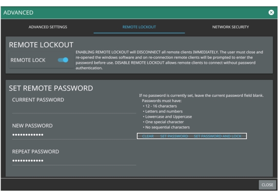
REMOTE LOCKOUT
Secure communication (Option 17) is not a time-limited option which creates a secure tunnel when connecting the instrument to a network. Refer to your product’s technical data sheet to get the listed of encrypted ports. Use the REMOTE LOCKOUT tab to enable remote lockout and set remote password:
• Enable REMOTE LOCK toggle on your instrument to disconnect all remote clients.
• Set a remote password in order to connect the instrument with the remote client’s ARRT software. The remote lockout feature is disabled by default and allows the remote connection to the instrument without any password authentication.
• Use SET REMOTE PASSWORD section to set a new remote password. Leave the CURRENT PASSWORD field empty if no password is currently set.
• Ensure to follow the password requirements, and press SET PASSWORD or SET PASSWORD AND LOCK options.
Remote Lockout
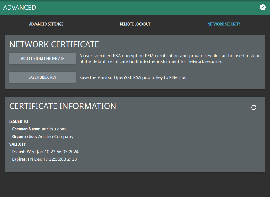
NETWORK SECURITY (Option 17)
Use network security tab to use a custom network certificate for additional security purposes:
• Press ADD CUSTOM CERTIFICATE to open the file manager and select an internally saved user specified RSA encryption PEM certificate and private key file instead of using an in-built network security certificate.
• Press SAVE PUBLIC KEY to save the Anritsu OpenSSL RSA public key to the PEM file.
Network Security
Reset Settings
1. Access the System menu (3-line icon in the upper left corner).
2. Select SETTINGS to access the instrument settings menu.
3. Select RESET to open the Reset menu.
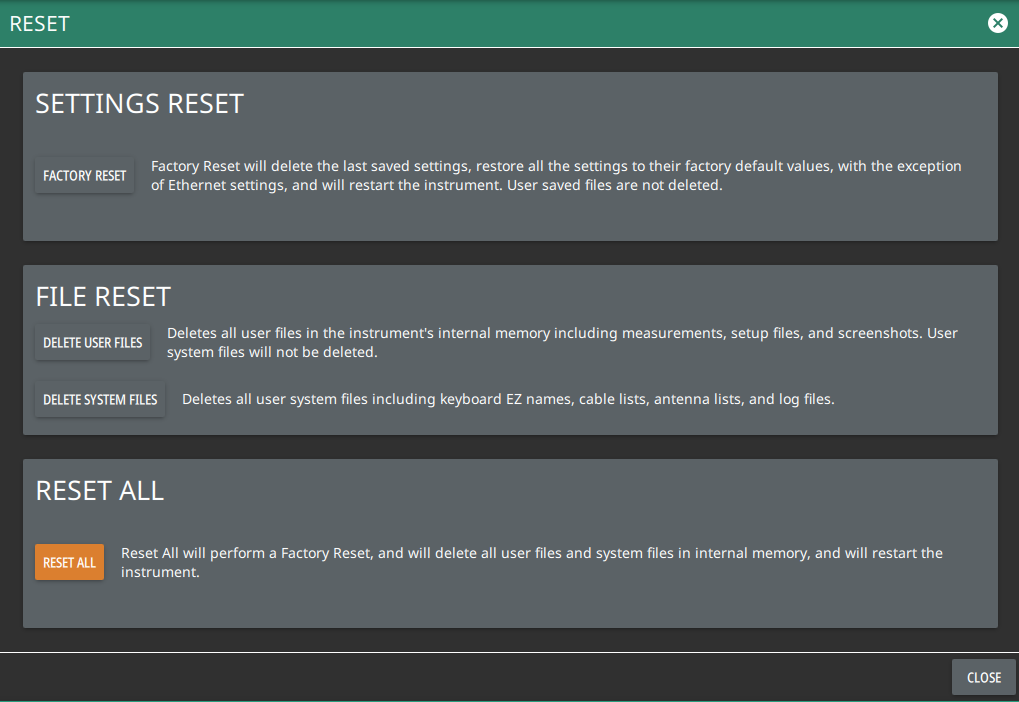
Reset Settings
The following reset options are available:
SETTINGS RESET
• FACTORY RESET: Restores the instrument to the factory default settings for all measurement modes and system settings, including language and the display and audio settings. Ethernet settings and user files are not affected. The instrument will automatically restart.
FILE RESET
• DELETE USER FILES: Deletes all user files from the instrument’s internal memory, including measurement, setup, and screenshot files. System files are not affected.
• DELETE SYSTEM FILES: Deletes all user system files from the instrument’s internal memory, including keyboard EZ names, cable and antenna lists, and log files. Other user files are not affected.
RESET ALL
• RESET ALL: Performs a Factory Reset as described above and deletes all user files and system files from the instrument’s internal memory. The instrument will automatically restart.