 |
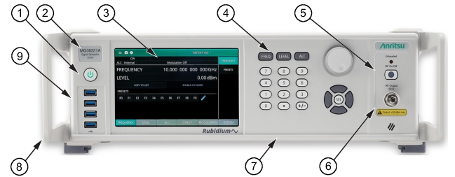
1. Power Button: Press the power button to power the signal generator on and off. Standby (off) is indicated by the white illuminated power button; Operate (on) is indicated by the green illuminated power button. 2. Model Identification Label: Identifies the model type and frequency range. 3. LCD Display: The LCD display provides information about the current status of the MG362x1A in a menu display format. This information includes the operating mode of the instrument and the value of the active frequency and power level parameters. The display functions as a touch-screen interface to provide access to graphical button controls and additional setting menus. 4. Front Panel Buttons: The front panel buttons provide controls for changing parameter values. 5. RF Output Control Key: The RF output control key turns the RF output power on and off. Output Off is indicated by an orange LED; Output On is indicated by a green LED. 6. RF Output Connector: The RF output connector provides the 50 Ω RF signal output. Before making connections to the RF output connector, see Torque Requirements. 7. Front Panel BNCs: Available with Option 29 (AM IN, FM IN, Pulse IN, External ALC IN). 8. Handles: Standard configuration includes handles. 9. USB Interface: Four front panel Type A USB Inputs. |