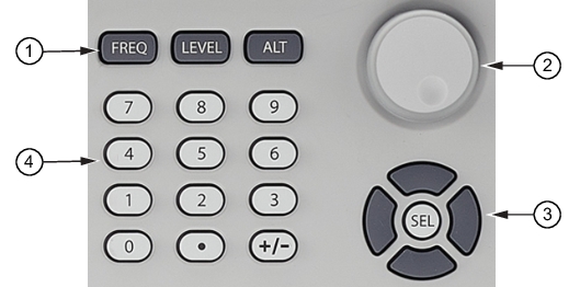
The value of a selected MG362x1A parameter can be changed using the numeric keypad, arrow hard buttons, or rotary data knob. The data entry area is identified in Figure: Front Panel Controls and described in the following paragraphs.
Front Panel Controls
1. Menu Hard Keys
2. Rotary Knob
3. Cursor Control Pad
4. Numeric Keypad
Menu Buttons
Frequency
Press to access the frequency menu.
Level
Press to access the level menu.
ALT
Non-Functional
Rotary Knob
The rotary knob can be used to change the value of a parameter that is open for editing. The cursor is moved under the open parameter using the left or right pad cursor control pads. Then, by slowly turning the knob clockwise or counterclockwise the value of the parameter is increased or decreased by the unit size. The unit size is determined by the cursor placement. Turn the knob rapidly changes the value in larger steps.
When editing frequency, power level, and time parameters, the incremental size can be set to a specific value using the system configuration increment menu. Refer to INCREMENT Menu. Once set and activated, each time the knob is turned clockwise or counter-clockwise, the parameter's value increases or decreases by the set amount.
Cursor Control Pad
The left and right pads control the direction of the cursor when editing a parameter. Press the left keypad to move the cursor left to edit an open parameter. Press the right keypad to move the cursor right to edit an open parameter. Press the top keypad to increase a units value, Press the bottom keypad to decrease the units value. Press and hold will allow the selected parameter to continually increase or decrease. Press Select to enter an opened single terminator value.
Numeric Keypad
The numeric keypad provides for entering frequency, power level, time, number-of-steps, modulation parameters, and GPIB address values. The “+/–” key functions as a “change sign” key during any keypad entry.
To avoid connector damage or inaccurate measurements, review document 10100-00031Connector Care Reference before making any connections.
N-Type Connector
Torque to 0.9 N-M (8in-lb) for standard N connectors using Anritsu Model 01-203 13/16 in Torque End Wrench.
K (2.92 mm) Connector
Torque to 0.9 Nm (8 lbf·in) using Anritsu Model 01-201 5/16 in Torque End Wrench and Anritsu Model 01-204 - 8 mm (5/16 in) Open End Wrench.
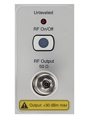
RF Output Panel
Unleveled Indicator
The unleveled indicator is displayed when the RF output goes unleveled and is normally caused by exceeding the specified leveled power rating.
RF On/Off
Press to manually turn RF output on or RF output off.
RF Output Connector
The female RF output connector. The 50 Ω output connector is K for the 20 GHz model MG36221A and K for the MG36241A model.
CAUTION Label
The output power may exceed +30 dBm. Attenuate output power as necessary to protect RF test equipment from excessive output power when connecting to the output connector.
Note
To prevent power losses due to an impedance mismatch, the mating connector and cable should also be rated at 50 Ω