To select Adjacent Channel Power (ACP) measurement go to main menu and press MEASURE > MEASUREMENT >ACP. The ACP measurements are set up using the SETUP Menu (5GNR ACP). Adjacent channel power is a measure of the power that leaks into adjacent transmit channels. The ACP measurement measures the power present in the transmit channel (refer to 5GNR Channel Power) along with the adjacent transmit channels that have been configured in the SETUP menu.
Adjacent Channel Power Ratio Measurement
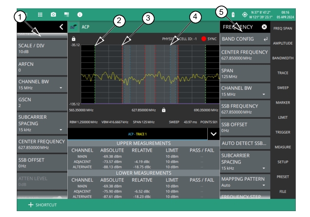
1. The status panel provides quick access to common spectrum analyzer settings. See Status Panel (5GNR OBW).
2. Green integration bandwidth edge of lower alternate channels.
3. Red integration bandwidth edge of lower adjacent and alternate channels.
4. Blue integration bandwidth edge of lower main and adjacent channels.
5. All ACP measurements parameters are set using setup menu. See SETUP Menu (5GNR ACP).
Frequency and span settings for many signal standards can be set as follows:
1. Select MEASURE on the main menu.
2. Select ACP from the MEASUREMENT button.
3. Select SETUP and then do the following:
• Channel Spacing
• Main Integration Bandwidth
• Adjacent Integration Bandwidth
• Alternate Integration Bandwidth
• Limit Testing
• Main Channel Limit
• Adjacent Channel Limit
• Alternate Channel Limit
Adjacent channel power is a constant measurement; after it is turned on, it remains on until a different measurement is selected or the sweep is paused. ACP is calculated at the end of each sweep.
SETUP Menu (5GNR ACP)
The Adjacent Channel Power SETUP menu is available in MEASURE > MEASUREMENT > ACP > SETUP. Once the ACP measurement is selected, the SETUP menu can be quickly accessed by tapping on the summary display area below the spectrum window.
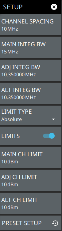
SETUP Menu (ACP)
CHANNEL SPACING
Sets the channel frequency spacing (center channel to center channel).
MAIN INTEG BW
Sets the range of integration used in calculating the power within the channel. The integration bandwidth (IBW) is displayed as two vertical dashed lines for each channel.
ADJ INTEG BW
Sets the range of integration bandwidth used in calculating the power in the adjacent channel.
ALT INTEG BW
Sets the range of integration used in calculating the power in the alternate channel.
LIMIT TYPE
Selects Absolute or Relative for the limit evaluation.
LIMITS
Turns on or off the use of ACP limits.
MAIN CH LIMIT
Sets the main channel limit.
ADJ CH LIMIT
Sets the adjacent channel limit.
ALT CH LIMIT
Sets the alternate channel limit.
PRESET SETUP
Sets all ACP setup parameters to default. Turns off limits.
STATUS PANEL (ACP)
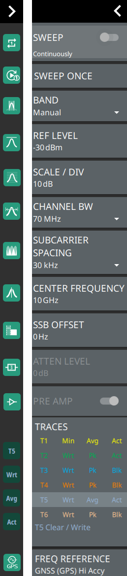
Below is the status panel with the corresponding minimized status panel icons for adjacent channel power measurement.
Status Panel with Minimized Status Panel Icons (ACP)
SWEEP
Toggles the current sweep setting between continuously or sweep once. Refer to Setting Sweep Parameters.
SWEEP ONCE
When sweep is set to single sweep, SWEEP ONCE updates the measurement display. Data continues to be captured in the background.
BAND
Select MANUAL, GLOBAL ALL or one of the predefined bands. Selecting MANUAL hides ARFCN and GSCN settings. Selecting a predefined band or GLOBAL ALL activates ARFCN and GSCN settings.
REF LEVEL
Sets the reference level of the top graticule line in the selected units. If the reference level offset is not zero, OFFSET REF LEVEL is displayed at this location. Refer to Setting Amplitude Parameters.
SCALE/DIV
Sets the graticule scale/division for log-based units. This setting does not apply to linear units.
CHANNEL BW
Sets the measurement channel bandwidth. The available bandwidth settings depend on the selected band and bandwidth option installed in the instrument. Refer to “Options Settings” section in Instrument Overview chapter of user guide.
SUBCARRIER SPACING
Sets the subcarrier spacing. The available input range is dependent on the selected band.
CENTER FREQUENCY
When the band is set to MANUAL, sets the center frequency of the measurement channel. Changing the center frequency sets the band to MANUAL.
SSB OFFSET
SSB is the Synchronous Signal Block. The SSB Offset sets the frequency offset between the SSB and the overall resource block.
ATTEN LEVEL
When auto attenuation is off, sets input attenuation.
Displays the current status of up to six traces in the status panel. The trace card includes the trace number, type, mode, and detector type. The active trace will show a highlighted background with the mode and detector type restated under the table. Selecting a trace in the status panel activates the pressed trace and opens the TRACE menu, allowing you to select and set up an individual trace as desired. Refer to Setting Trace Parameters.
FREQ REFERENCE
Indicates the current frequency reference source of Internal High Accuracy (used after GPS has lost sync, but while the internal clock still has good GPS reference), Internal Standard Accuracy, External, or GNSS (GPS) Hi Accy (requires GPS). The instrument automatically selects the frequency reference in the following order of priority: external, GPS, then the internal time base.