![]() |
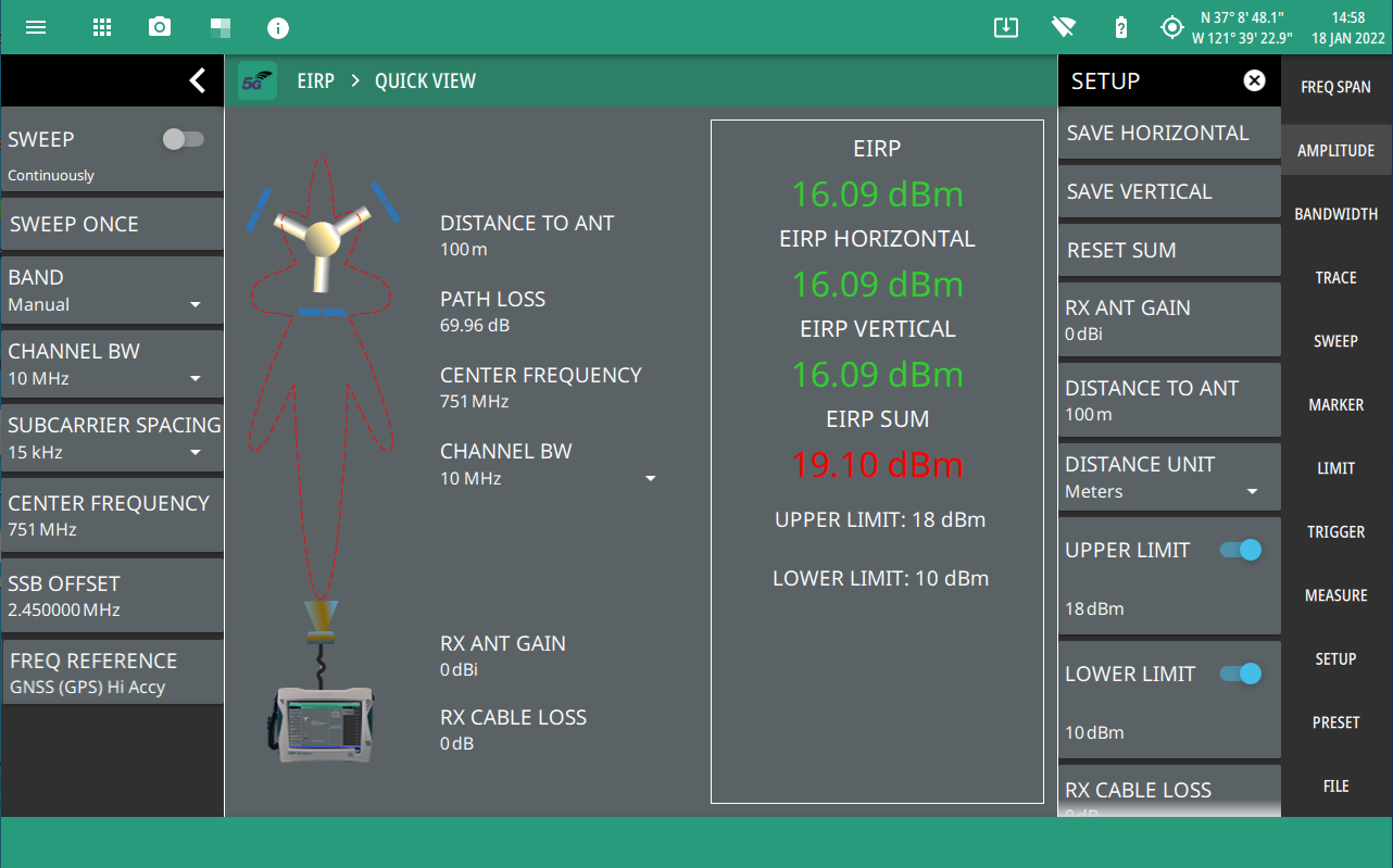
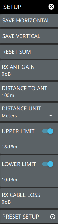
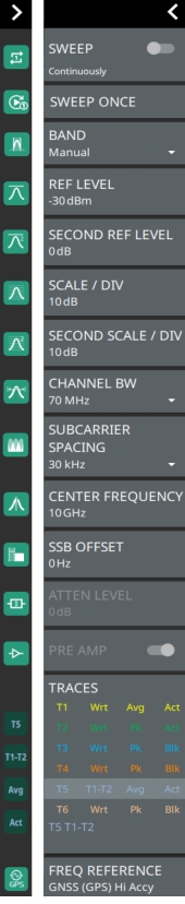
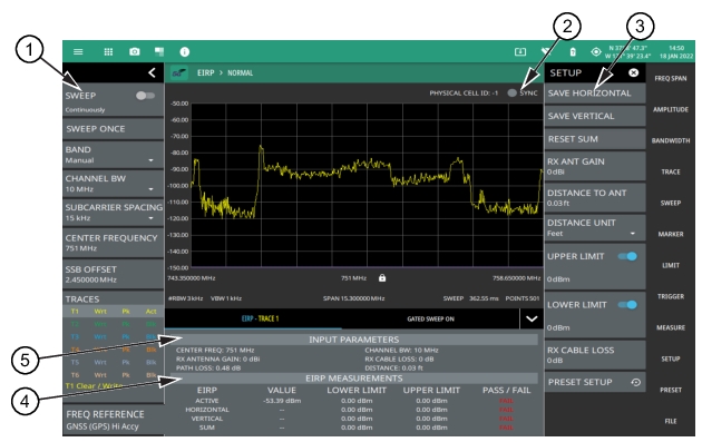
1. 5GNR Analyzer Status Panel: Each measurement features a unique status panel that displays settings and information relevant to the current measurement and view settings. This panel provides quick access to the measurement frequency, subcarrier spacing, channel bandwidth, and band configuration. See Status Panel (5GNR EIRP). 2. SYNC: Valid 5GNR occupied bandwidth measurements require signal synchronization. The indicator here blinks green when the received signal is synchronized, indicating that you have a valid measurement. 4. EIRP Measurement Summary: This area shows the measurement results summary with pass/fail test results, when enabled: • The ACTIVE EIRP value and upper/lower test limits are expressed in dBm with a pass/fail result. • The saved HORIZONTAL EIRP value with upper/lower test limits expressed in dBm with a pass/fail result. • The saved VERTICAL EIRP value with upper/lower test limits expressed in dBm with a pass/fail result. • The effective sum of the saved HORIZONTAL and VERTICAL EIRP values, with upper/lower test limits expressed in dBm with a pass/fail result. • Tapping this summary area opens the EIRP SETUP menu. 5. EIRP Input Parameters: This area shows the input parameters for the measurement: • Gate delay and length parameters are applied when gated sweep is enabled (requires Option 90). See Gated Sweep (Option 90). • The frequency and band parameters are configured in the BAND CONFIG menu. See BAND CONFIG Menu. • Receiver antenna gain parameters are configured in the EIRP SETUP menu. See SETUP Menu (5GNR EIRP). |
![]() |
- ![]() | SAVE HORIZONTAL Saves the current EIRP measurement as the horizontally polarized EIRP value. The antenna must be set up for horizontal polarization for a valid measurement. SAVE VERTICAL Saves the current EIRP measurement as the vertically polarized EIRP value. The antenna must be set up for vertical polarization for a valid measurement. RESET SUM Clears the saved horizontal and vertical EIRP measurements and resets the sum. RX ANT GAIN Sets the antenna gain value from 0 dBi to 999 dBi with a resolution of 0.01 dB. For the most accurate reading, any cable loss between the antenna and the instrument should be subtracted from the RX ANT GAIN. DISTANCE TO ANT Sets the straight line distance between the antenna and signal source. The range can be set from 1 m to 1000 m (approximately 3.3 ft to 3300 ft) with a resolution of 0.01 (m or ft). DISTANCE UNIT Sets the distance unit of measure to Meters or Feet. UPPER LIMIT Enables the pass/fail compliance test for the upper radiated power. Once enabled, the settable range is –99 dBm to 100 dBm. LOWER LIMIT Enables the pass/fail compliance test. Once enabled, the settable range is –99 dBm to 100 dBm. RX CABLE LOSS Sets the cable loss parameter in dB/m. PRESET SETUP Presets the SETUP menu to default settings. |
![]() | SWEEP Toggles the current sweep setting between continuously or sweep once. Refer to Setting Sweep Parameters. SWEEP ONCE When sweep is set to single sweep, SWEEP ONCE updates the measurement display. Data continues to be captured in the background. BAND Select MANUAL, GLOBAL ALL or one of the predefined bands. Selecting MANUAL hides ARFCN and GSCN settings. Selecting a predefined band or GLOBAL ALL activates ARFCN and GSCN settings. REF LEVEL Sets the reference level of the top graticule line in the selected units. If the reference level offset is not zero, OFFSET REF LEVEL is displayed at this location. SCALE/DIV Sets the graticule scale/division for log-based units. This setting does not apply to linear units. SECOND SCALE/DIV It applies to second reference level and is available only when trace math is enabled. CHANNEL BW Sets the measurement channel bandwidth. The available bandwidth settings depend on the selected band and bandwidth option installed in the instrument. Refer to “Options Settings” section in Instrument Overview chapter of user guide. SUBCARRIER SPACING Sets the subcarrier spacing. The available input range is dependent on the selected band. CENTER FREQUENCY When the band is set to MANUAL, sets the center frequency of the measurement channel. Changing the center frequency sets the band to MANUAL. SSB OFFSET SSB is the Synchronous Signal Block. The SSB Offset sets the frequency offset between the SSB and the overall resource block. ATTEN LEVEL When auto attenuation is off, sets input attenuation. PRE AMP Toggles the low-noise front-end preamplifier on or off. Refer to Setting Amplitude Parameters. TRACES Displays the current status of up to six traces in the status panel. The trace card includes the trace number, type, mode, and detector type. The active trace will show a highlighted background with the mode and detector type restated under the table. Selecting a trace in the status panel activates the pressed trace and opens the TRACE menu, allowing you to select and set up an individual trace as desired. Refer to Setting Trace Parameters. FREQ REFERENCE Indicates the current frequency reference source of Internal High Accuracy (used after GPS has lost sync, but while the internal clock still has good GPS reference), Internal Standard Accuracy, External, or GNSS (GPS) Hi Accy (requires GPS). The instrument automatically selects the frequency reference in the following order of priority: external, GPS, then the internal time base. |