Site Master™ MS2085A/MS2089A User Guide : Instrument Messages and Troubleshooting : System Recovery
 
System Recovery
 
This section can be referred to in the event the MS2085A/89A does not boot properly and the normal attempts to restart the instrument have failed.
Introduction
If the MS2085A/89A fails to boot properly, a second boot attempt will load a recovery menu as shown in Figure: Recovery Mode. This menu is only displayed when the instrument fails a normal boot process. A failure to boot properly might not indicate a problem. A boot disruption, such as removing power before the instrument can complete the boot process, will initiate a recovery menu on the next boot.
Recovery Mode 
If you see this screen:
1. Select the REBOOT INSTRUMENT button once the recovery menu loads.
2. If boot failure continues, a system recovery can be performed by pressing CONTINUE TO RECOVERY MODE.
The Recovery Mode menu (Figure: Recovery Mode) shows instrument information and provides a variety of recovery options in ascending invasive order:
1. Select REBOOT to reboot the instrument without any further action.
2. Save all internal user files and logs by inserting a USB device and press the EXPORT button.
3. Refer to Reset for information about various reset options.
4. Refer to Boot Order to select a different boot order.
5. Refer to Install SW to SLOT X to reload or update the system software.
Recovery Mode 
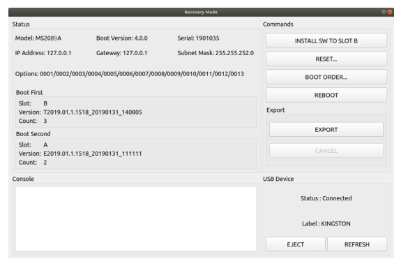
Status
Shows the Model, Boot Version, Serial Number of the MS2085A/89A, IP Address, Gateway, Subnet Mask.
Options
Shows the Options currently installed.
Boot First
Shows the Slot, Version, and Count in the Boot First position.
Boot Second
Shows the Slot, Version, and Count in the Boot Second position.
Console
Provides a readout of the reboot activity.
Commands
Choose the command method to restart the instrument:
INSTALL SOFTWARE TO SLOT B: Indicates which slot will be overwritten as described in Install SW to SLOT X
RESET: Provides the RESET dialog as shown in Reset.
BOOT ORDER: Provides the Boot Order dialog as shown in Boot Order.
REBOOT: Reboots the instrument.
Export
Select EXPORT to save all internal user files and logs to a USB device. Select CANCEL to cancel the export. The saved files can be copied back to internal memory by using the file management menus.
USB Device
This section provides:
Status: The USB memory device is connected or unconnected.
Label: The Manufacturer of the USB memory device.
EJECT: Select to eject and remove the USB memory device.
REFRESH: Select to reconnect to the USB memory device.
Reset
The recovery RESET dialog is shown in Figure: RESET Dialog. Here you can reset the MS2085A/89A from the choices shown. In rare cases, system, internal, or other user files may interfere with instrument operation, so choosing to delete this data in that order may resolve a problem.
Caution 
Any data that is deleted by the following selections is unrecoverable. Use the EXPORT button to save this data before proceeding.
Once reset options are selected, press the RESET SELECTED button.
RESET Dialog
-
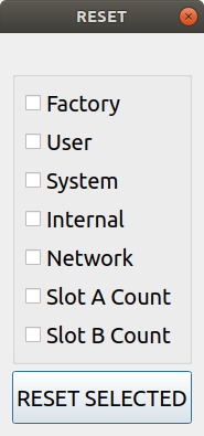
Factory
Performs a Factory reset, which deletes last saved settings files for all applications.
User
Performs a User reset, which deletes all user setup, measurement, csv, limit, screenshot, IQ captures, and user calibration files.
System
Performs a Factory reset and also deletes event and error logs.
Internal
For service use only. Performs an Internal reset, which deletes non-volatile system files, except for critical files such as the serial number, options, and network configuration. Does not take effect until the next boot.
Network
Performs a Network reset, which deletes manual Ethernet settings and reverts the networking to DHCP. All saved Wireless networks will also be lost.
Slot A Count
Resets Slot A Count to 3. This is used for the recovery mode countdown.
Slot B Count
Resets Slot B Count to 3. This is used for the recovery mode countdown.
RESET SELECTED
Resets the MS2085A/89A by the method chosen.
Boot Order
The order of which slot boots first can be changed from the BOOT ORDER menu (shown in Figure: BOOT ORDER). You may want to change the boot order to select a different software image in case of corruption or for preference. Selecting SWAP will change the boot sequence order: Slot A or Slot B. Once selected, press CLOSE and then reboot the instrument. This setting can only be changed from the Recovery Mode menu.
BOOT ORDER
-
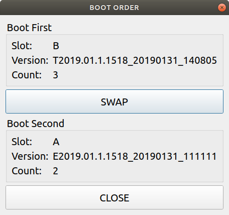
Boot First
Provides the first boot version to boot.
Slot: Provides the slot designated location.
Version: Provides the boot version number.
Count: Boot attempts with this version.
SWAP
Swap Slot A and Slot B in the boot sequence.
Boot Second
Provides the first boot version to boot.
Slot: Provides the slot designated location.
Version: Provides the boot version number.
Count: Boot attempts with this version.
Close
Closes the BOOT ORDER dialog.
Install SW to SLOT X
The recovery mode shows two slots (A and B). These slots contain different system software packages that are installed. Each slot contains the following information:
Slot name (A,B): Boot version package (A or B).
Slot count (3,2,1): The count indicates how many unsuccessful boot attempts before the slot is marked as unbootable. Every failed attempt decrements the value until it reaches 0 (unbootable). This count can be reset to 3 using the Reset menu.
Slot version: The version represents the software package version available in the slot.
You can install a new software package by inserting a USB memory device with the system software file (.raucb) and pressing “Install SW to SLOT X.” The X will be replaced with an A or B depending on which slot is to be overwritten. You will not be able to select which system software file will be installed from the attached USB, it will always install the first one found.