 |
|
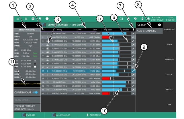 |
1. Status Panel: This menu provides a quick access to common settings used for power meter measurements. Refer to Status Panel (Bar Chart View). 2. Plus Icon: Press this icon to add channels. Alternatively, press SETUP menu and select ADD CHANNELS. 3. Technology Icon: This icon shows the mini icon of the selected frequency band. 4. Bar Chart View: Displays the list of channel indicated in horizontal bars. The channel parameters such as frequency, span, channel power and reference level are included at the top of the bar chart view. The blue bar indicates that the channel power value is within the set upper or lower limit range. The red bar indicates that the channel power value exceeds the upper/lower limit range. 5. Limit Line: The white dashed line is the limit line. 6. Maximum Limit Line: The solid white line on the horizontal bar is the maximum channel power value measured for any given channel. 7. Trash Can Icon: Press this icon to delete all the channels. 9. Edit Icon: Select this icon to edit the channel parameters. Using the edit icon you can delete a single channel, or apply any changes made to the listed parameters. 10. Minimum Limit Line: The solid black line on the horizontal bar represents the minimum channel power value measured for any given channel. 11. Strip Chart: Displays the strip chart view of the selected measurement channel. Refer to Strip Chart View. |
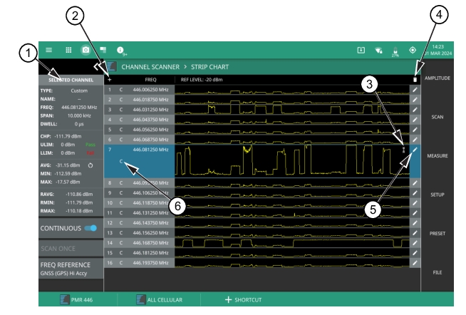 |
1. Status Panel: This menu provides quick access to common settings used for power meter measurements. Refer to Strip Chart View. 2. Plus Icon: This icon acts like a quick shortcut to add channels. 3. Expand/Collapse Icon: This icon allows to either expand or collapse the horizontal strip of a given channel. 4. Trash Can Icon: Select this icon to delete all the channels. 5. Edit Icon: Select this icon to edit the channel parameters.. 6. Technology Icon: This icon represents official frequency band or custom band name. |