LTE FDD/TDD Signal Analyzer Measurement Guide : LTE Analyzer (Option 883) : Setting Amplitude
 
Setting Amplitude
Amplitude-related parameters are set using the AMPLITUDE Menu.
Setting Amplitude Parameters
The LTE measurement has two different types of amplitude settings, one for the data capture used to decode the signal internally, and one for the display. The amplitude range refers to the amplitude level used to capture the data. The amplitude reference level is typically an absolute reference level set at the top of the graticule for the power level being measured. Signal levels above this set value will be outside of the display range and may overdrive and saturate the input circuit (refer to Indications of Excessive Signal Level). To set the current amplitude reference level:
1. To automatically set optimum settings, press AMPLITUDE > AUTO RANGE. The instrument will dynamically update the attenuation and preamp settings for the capture. AUTO RANGE helps ensure that harmonics and spurs are not introduced into the measurements while giving enough power to accurately decode the signal. When auto range is on, the amplifier and preamp cannot be set manually and the reference level is only used to adjust the top end of the y-axis of the plot or graph.
2. To manually set the range and reference level, press AMPLITUDE > REF LEVEL, then enter the desired reference level in dBm, or use the AUTO REF LEVEL (available when AUTO RANGE is disabled). This will set the attenuation and preamp for both the plot and the capture.
Reference Level Offset for External Loss or External Gain
To obtain accurate measurements, you can compensate for any external attenuation or gain by using a reference level offset. The compensation factor is in dB. External attenuation can be created by using an external cable or an external high power attenuator. External gain is typically from an amplifier.
To adjust the reference level for either gain or loss:
1. Press AMPLITUDE > REF LEVEL OFFSET.
2. Enter a positive dB value to account for gain or enter a negative dB value to account for loss.
3. The new reference level offset value will be displayed on the instrument and the reference level is adjusted accordingly.
Attenuator Functions
The spectrum analyzer includes a step attenuator at the RF input. This attenuator is used to reduce large signals to levels that make best use of the analyzer’s dynamic range. Normally, the input attenuation automatically adjusts as a function of reference level. In the AMPLITUDE menu, the ATTEN LEVEL allows manual adjustment of the input attenuation. When auto attenuation is selected, both the reference level and the attenuation are increased. The following actions, listed in decreasing order of effectiveness, can facilitate the detection of low-level CW signals:
Decrease the reference level and attenuation. Refer to AMPLITUDE Menu.
Turn on the preamplifier.
For RF-based measurements:
Reduce RBW and or VBW (RBW/VBW = 10 is often optimal for this purpose). Refer to Setting Bandwidth Parameters.
Use trace averaging if VBW is already set to 1 Hz.
Indications of Excessive Signal Level
The instrument has built-in features to help prevent input overload. These include auto attenuation and reference level. The instrument will also indicate when a received signal is too high for the current setup by displaying an “ADC Overrange” notification in the title bar (Figure: ADC Overrange). Before proceeding with the measurements, adjust the reference level, the attenuation level, and disable the preamplifier if necessary. Adjusting the resolution bandwidth and frequency range may also help when measuring small signals that are near large signals.
ADC Overrange
Overpower Warning
The Field Master Series MS2080A/MS2070A and Site Master MS2089A instruments are equipped with an in-built overpower protection hardware in order to manage considerably high range of input power. If the input power range exceeds beyond 5 watts, the protection relay gets activated and a notification alert is displayed as shown in the Figure: Overpower Warning. Proceed by removing the high power input source to avoid to damaging the RF circuitry.
 
Overpower Warning
 
AMPLITUDE Menu
The AMPLITUDE menu is available in all LTE measurements.
AMPLITUDE Menu (LTE Measurements)
-
 
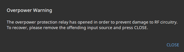
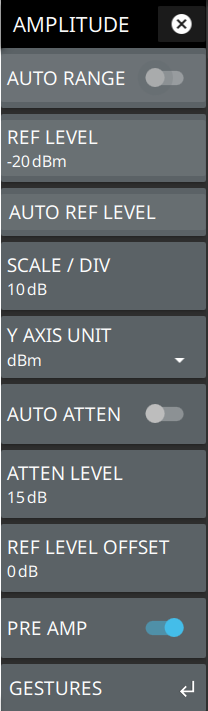
AUTO RANGE
The instrument will dynamically update the attenuation and preamp settings for the measurement. Auto range helps ensure that harmonics and spurs are not introduced into the measurements.
OFFSET REF LEVEL
The reference level is the top graticule line on the measurement display. If the reference level offset is not zero, the offset reference level is displayed at this menu location. If auto range is enabled, the reference level is graphical only and will have no impact on attenuation or preamp.
AUTO REF LEVEL
Auto reference level will change the reference value so as to place the highest signal amplitude at about two graticule lines from the top. This feature is not available when auto range is enabled.
SCALE/DIV
The scale can be set from 1 dB per division to 15 dB per division. The default setting is 10 dB.
Y AXIS UNIT
Selects the y-axis amplitude units of dBm, dBW, or dBµV, etc.
AUTO ATTEN
Input attenuation can be either tied to the reference level (on) or manually selected (off). When input attenuation is tied to the reference level, attenuation is increased as higher reference levels are selected to make sure the instrument input circuits are not saturated by large signals that are likely to be present when high reference levels are required. Auto attenuation is not available when auto range is enabled.
ATTEN LEVEL
Manually sets the attenuation level. This feature is not available when auto range or auto attenuation is enabled.
REF LEVEL OFFSET
Reference level offset compensates for the presence of external input attenuation or gain. The default offset value is 0 dB. The reference level on the Y-axis will reflect the new offset value. For example, if the reference level was 0 dBm and an offset value of –10 dB is applied, the offset reference level will be 10 dBm.
PRE AMP
Turns the low-noise front-end preamplifier on or off. To ensure accurate measurement results, the largest signal into the instrument input when the preamplifier is turned on should be less than –40 dBm. The preamplifier cannot be turned on if auto attenuation is on and reference level is above –40 dBm.
GESTURES
Opens the GESTURES Menu. Not shown in LTE Modulation measurements.