 |
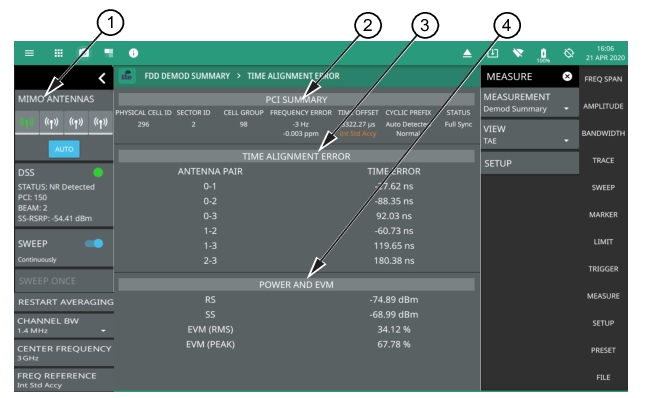
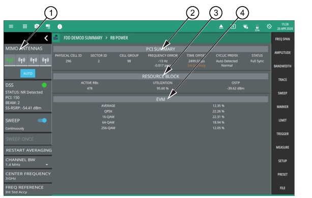
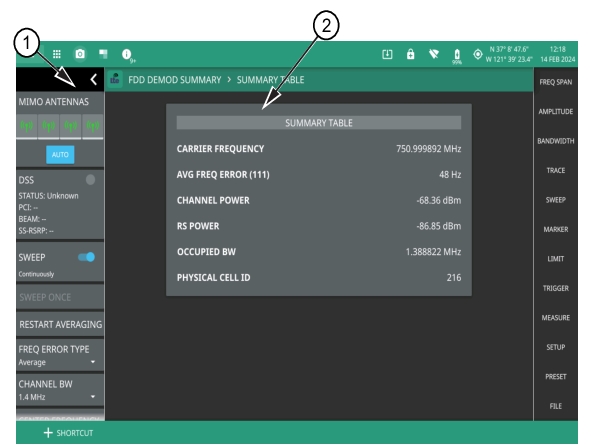
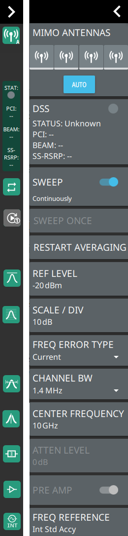
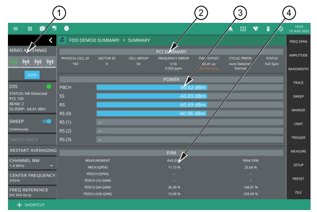
1. LTE Analyzer Status Panel: Each measurement features a unique status panel that displays settings and information relevant to the current measurement and view settings. This panel provides quick access to the MIMO antenna selection and status, sweep setting, and frequency and bandwidth configuration. See Status Panel (LTE Demod Summary). 2. PCI Summary: This area shows the physical cell ID, including the sector ID, cell group number, frequency error, time offset, and sync status. Sync status can indicate if there is a PSS or SSS failure, a Full Sync, or an Unknown condition. Also noted is the instrument’s reference clock accuracy of Internal, External, or GNSS (GPS) high accuracy (requires GPS). 3. Power Summary: Shows the received power for each of the following: • PBCH: Physical broadcast channel, the main purpose of which is to carry the broadcast information block. • SS: Synchronization signal is used as a preamble sequence in LTE for synchronization purposes. • RS: Reference signal is used as a pilot subcarrier for channel estimation and tracking in LTE. • RS (0 through 3): Reference signal power of each of the MIMO antennas. 4. EVM Summary: Shows the RMS (%) of the error vectors between the reconstructed ideal signals and the received signals, divided by the RMS value of the ideal signals. The first column lists the average EVM (rms) value and the second column lists the peak measured value for each of the following as they are received: • PBCH (QPSK): Physical broadcast channel, the main purpose of which is to carry the broadcast information block. • PDSCH (QPSK): Physical downlink shared channel (quadrature phase shift keying). • PDSCH (16-QAM, 64-QAM, 256-QAM): Physical downlink shared channel (quadrature amplitude modulation; 16, 64, and 256 states). |