LTE FDD/TDD Signal Analyzer Measurement Guide : LTE Analyzer (Option 883) : LTE Multi PCI
 
LTE Multi PCI
To select multi PCI measurement go to main menu and press MEASURE > MEASUREMENT >Multi PCI. The multi PCI measurements are set up using the SETUP Menu (LTE Multi PCI). The following measurement is set up to display LTE Multi PCI data. The multi PCI displays the measurement results of every detected beam in a single, sortable table with a bar graph of the selected measurement.
LTE Multi PCI
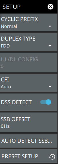
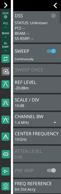
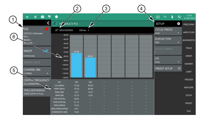
1. LTE Analyzer Status Panel: Each measurement features a unique status panel that displays settings and information relevant to the current measurement and view settings. This panel provides quick access to the measurement frequency and band configuration. See Status Panel (LTE Multi PCI).
2. Sort: Sets the selected measurement sort order of Descending or Ascending.
3. Bar Graph Measurement: Selects which measurement is plotted on the bar graph (RSRP, RSRQ, SINR, PCI, SS Power).
4. SETUP Menu: The control channel measurement settings are configured in the SETUP menu. See SETUP Menu (LTE Multi PCI).
5. Table Display: fields show the beam index value of the corresponding physical-layer cell ID.
PCI: These fields show the physical-layer cell ID number. When PCI is selected for the bar graph measurement, the values can be sorted in ascending or descending order by tapping the sort button in the bar graph header.
S-SS (dBm): These fields show the secondary synchronization signal power of the corresponding physical-layer cell ID, measured in dBm. When SSPower is selected for the bar graph measurement, the values can be sorted in ascending or descending order by tapping the sort button in the bar graph header.
RSRP (dBm): These fields show the reference signal received power, the average power of resource elements (RE) that carry cell-specific reference signals (RS) over the entire bandwidth. When RSRP is selected for the bar graph measurement, the values can be sorted in ascending or descending order by tapping the sort button in the bar graph header.
RSRQ (dB): These fields show the reference signal received quality, which provide additional information when RSRP is not sufficient to make a reliable handover or cell reselection decision. RSRQ is the ratio between RSRP and RSSI measured in dB. When RSRQ is selected for the bar graph measurement, the values can be sorted in ascending or descending order by tapping the sort button in the bar graph header.
SINR (dB): These fields show the signal-to-noise and interference ratio of the corresponding physical-layer cell ID, measured in dB. When SINR is selected for the bar graph measurement, the values can be sorted in ascending or descending order by tapping the sort button in the bar graph header.
AVG EVM (%): Shows the dominant cell’s AVG EVM of all of the error vectors between the reconstructed ideal signals and the received signals, divided by the RMS value of the ideal signals.
PEAK EVM (%): Shows the dominant cell’s peak EVM of all of the error vectors between the reconstructed ideal signals and the received signals, divided by the RMS value of the ideal signals.
FREQ ERROR (Hz and PPM): This is the difference between the measured carrier frequency and the specified carrier frequency of the dominant cell. This number is only as accurate as the frequency reference that is used, and is typically only useful with a good external frequency reference or GNSS (GPS).
DOMINANCE (dB): Dominance is the ratio of the dominant cell’s power for the largest signal to the sum of all other signals found, measured in dB.
6. Bar Graph Display: Shows the selected measurement as a bar graph with the current value at the top of the graph.
SETUP Menu (LTE Multi PCI)
The SETUP menu is available in MEASURE > MEASUREMENT > Multi PCI > SETUP.
LTE SETUP Menu (LTE Multi PCI)
-
 
CYCLIC PREFIX
Sets the cyclic prefix (or guard time interval) to Normal, Extended, or Auto. The cyclic prefix is a duplication of a fraction of the symbol end. This setting affects the OFDM symbol sensitivity to time dispersion.
DUPLEX TYPE
Selects either frequency division duplex (FDD) or time division duplex (TDD).
UL/DL CONFIG
Available only in TDD duplex type. Sets the uplink/downlink (UL/DL) configuration, or Frame Format. This selection determines which sub-frames are uplink sub-frames and which are downlink sub-frames, and where the transitions between uplink and downlink sub-frames occur.
CFI
Selects the control format indicator (CFI) which indicates how many OFDM symbols are used for carrying the control channel at each sub-frame. CFI1 uses the first symbol at the sub-frame for PDCCH allocation. CFI2 uses the first and the second symbol for PDCCH. CFI3 uses the first three symbols for PDCCH.
DSS DETECT
Detects the Dynamic Spectrum Sharing (DSS) signal when turned On. This toggle only applies to FDD duplex type.
SSB OFFSET
SSB is the synchronous signal block. The SSB offset sets the frequency offset between the SSB and the center frequency of the channel. Negative values result in an offset lower than the center frequency. Positive values result in an offset higher than the center frequency.
AUTO DETECT SSB OFFSET
When DSS DETECT is toggled On, automatic detection of the SSB Offset is enabled.
PRESET SETUP
Presets the SETUP menu to default settings.
Status Panel (LTE Multi PCI)
The status panel illustrated in this section is unique to the current analyzer and to the particular measurement and view that is selected.
Figure: Status Panel (LTE Multi PCI Measurement) shows the LTE status panel that covers the LTE Multi PCI measurements.
Status Panel (LTE Multi PCI Measurement) 
 
DSS: Displays the status of the detected DSS signal in addition to PCI, BEAM, SS-RSRP values.
SWEEP: Toggles the current sweep setting between continuously or sweep once.
SWEEP ONCE
When sweep is set to single sweep, SWEEP ONCE updates the measurement display. Data continues to be captured in the background.
REF LEVEL
Sets the reference level of the top graticule line in the selected units. If the reference level offset is not zero, OFFSET REF LEVEL is displayed at this location. Refer to Setting Amplitude.
SCALE/DIV
Sets the graticule scale/division for log-based units. This setting does not apply to linear units.
CHANNEL BW
Sets the measurement channel bandwidth.
CENTER FREQUENCY
Sets the center frequency of the measurement channel.
ATTEN LEVEL
When auto attenuation is off, sets input attenuation.
PRE AMP
Toggles the low-noise front-end preamplifier on or off. Refer to Setting Amplitude.
FREQ REFERENCE
Indicates the current frequency reference source of Internal, External, or GNSS (GPS) Hi Accuracy (requires GPS). The instrument automatically selects the frequency reference in the following order of priority: external, GPS, then the internal time base.