LTE FDD/TDD Signal Analyzer Measurement Guide : LTE Analyzer (Option 883) : LTE Carrier Aggregation
 
LTE Carrier Aggregation
To select carrier aggregation measurement go to main menu and press MEASURE > MEASUREMENT >Carrier Aggregation. The carrier aggregation measurements are set up using the SETUP Menu (LTE Carrier Aggregation). LTE carrier aggregation measurements are used for compliance testing of 3GPP LTE networks and can evaluate active antenna systems for dynamic physical layer attributes and received power levels of the transmitted signal. Carrier aggregation displays up to eight component carrier (CC) measurements. Each carrier can be set up uniquely for signal band. An example LTE carrier aggregation measurement is shown in Figure: LTE Carrier Aggregation Measurement.
LTE Carrier Aggregation Measurement
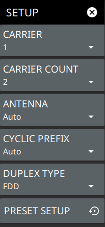
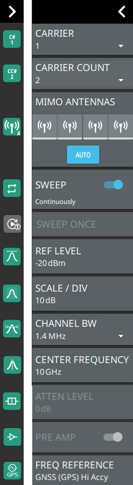
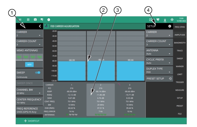
1. LTE Analyzer Status Panel: Each measurement features a unique status panel that displays settings and information relevant to the current measurement and view settings. This panel provides quick access to the MIMO antenna selection and status, current carrier and carrier count, sweep setting, and channel bandwidth configuration. See Status Panel (LTE Carrier Aggregation).
2. Signal Level: This area shows a bar graph of the signal level of the specific carrier.
3. Summary Display: Shows data for each numbered component carrier. The highlighted summary display area is the component carrier data that can be edited, and this area can be touched to select that component carrier for editing. A rotating magenta circle indicates which carrier is currently being measured.
Physical Cell ID (PCI) identifying information sent by the transmitter in the sync signal.
Reference signal received power (RSRP) measured in dBm indicates the average power received from a single Reference signal or the level of the received signal from the base station.
Reference signal received quality (RSRQ) measured in dB indicates the quality of the received signal.
Signal interference and noise (SINR) ratio measured in dB is the ratio of the signal level to the noise level. Higher the value, the better is the signal quality.
Center frequency of the measurement channel.
Channel bandwidth (BW) sets the bandwidth of the component carrier.
EVM (RMS) shows the percentage value of all the error vectors between the reconstructed ideal signals and the received signals divided by the RMS value of the ideal signals.
Frequency error is the difference between the measured carrier frequency and the specified carrier frequency. This measurement is only as accurate as the frequency reference that is used and is typically only useful with a good external frequency reference or GNSS (GPS).
Antennas show the selected MIMO antenna for the specific carrier.
4. SETUP Menu: The component carrier settings are configured in the SETUP menu. See SETUP Menu (LTE Carrier Aggregation).
SETUP Menu (LTE Carrier Aggregation)
The carrier aggregation SETUP menu is available in MEASURE > MEASUREMENT > Carrier Aggregation > SETUP.
LTE SETUP Menu (Carrier Aggregation)
-
 
CARRIER
Selects the component carrier to make active. The active carrier is highlighted in the summary display area and any setting changes will apply to the active carrier. Note that the active carrier is not necessarily the one that is currently being measured.
CARRIER COUNT
Sets the number of carriers to be displayed on the screen and to be measured.
ANTENNA
Sets the MIMO antenna number (0 to 3, or AUTO) to use during a measurement. AUTO will use the antenna with the highest received signal power.
CYCLIC PREFIX
Sets the cyclic prefix (or guard time interval) to Normal, Extended, or Auto. The cyclic prefix is a duplication of a fraction of the symbol end. This setting affects the OFDM symbol sensitivity to time dispersion.
DUPLEX TYPE
Selects either frequency division duplex (FDD) or time division duplex (TDD).
PRESET SETUP
Presets the SETUP menu to default settings.
Status Panel (LTE Carrier Aggregation)
The status panel illustrated in this section is unique to the current analyzer and to the particular measurement and view that is selected.
Figure: Status Panel (LTE Carrier Aggregation Measurement) shows the LTE status panel that covers the LTE carrier aggregation measurement.
Status Panel (LTE Carrier Aggregation Measurement) 
 
CARRIER
Selects the component carrier to make active. The active carrier is highlighted in the summary display area.
CARRIER COUNT
Sets the number of carriers to be displayed on the screen and to be measured.
MIMO ANTENNAS: Toggles the current MIMO antenna setting between AUTO or to select one of the available antennas. When a single antenna is selected, a blue underscore will appear below the antenna icon. The antenna icon is highlighted green when receiving a signal.
SWEEP: Toggles the current sweep setting between continuously or sweep once.
SWEEP ONCE
When sweep is set to single sweep, SWEEP ONCE updates the measurement display. Data continues to be captured in the background.
REF LEVEL
Sets the reference level of the top graticule line in the selected units. If the reference level offset is not zero, OFFSET REF LEVEL is displayed at this location. Refer to Setting Amplitude.
SCALE/DIV
Sets the graticule scale/division for log-based units. This setting does not apply to linear units.
CHANNEL BW
Sets the measurement channel bandwidth. The available bandwidth settings depend on the selected band and bandwidth option installed in the instrument.
CENTER FREQUENCY
Sets the center frequency of the measurement channel.
ATTEN LEVEL
When auto attenuation is off, sets input attenuation.
PRE AMP
Toggles the low-noise front-end preamplifier on or off. Refer to Setting Amplitude.
FREQ REFERENCE
Indicates the current frequency reference source of Internal, External, or GNSS (GPS) Hi Accuracy (requires GPS). The instrument automatically selects the frequency reference in the following order of priority: external, GNSS (GPS), then the internal time base.