![]() |
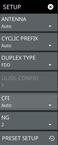
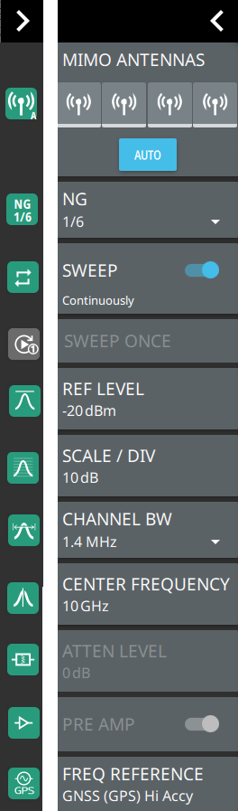
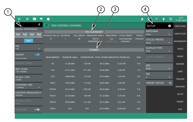
1. LTE Analyzer Status Panel: Each measurement features a unique status panel that displays settings and information relevant to the current measurement and view settings. This panel provides quick access to the MIMO antenna selection and status, NG parameter, sweep setting, and channel bandwidth configuration. See Status Panel (LTE Control Channel). 2. PCI SUMMARY: This area shows the physical cell ID, including the sector ID, cell group number, frequency error, time offset, cyclic prefix, and sync status. Sync status can indicate if there is a PSS or SSS failure, a Full Sync, or an Unknown condition. Also noted is the instrument’s reference clock accuracy of Internal, External, or GNSS (GPS) high accuracy (requires GPS). 3. POWER: Shows power levels in dBm and watts of each physical layer control: • Reference Signal (RS) Power: The reference signal is used for downlink channel estimation. • Primary Synchronization Signal (P-SS) Power. The primary sync signal is used to obtain slot synchronization. It contains information needed for cell search. • Secondary Synchronization Signal (S-SS) Power: The secondary sync signal is used to obtain frame synchronization and cell identity. It contains information needed for cell search. • Physical Broadcast Channel (PBCH) Power: This physical channel carries system information for user equipment (UE) requiring access to the network. • Physical Control Format Indicator Channel (PCFICH) Power: This channel provides information to enable the UE to decode the PDCCH and PDSCH channels. • Physical Hybrid Automatic Repeat Request Indicator Channel (PHICH): Transmits the channel coded HARQ indicator codeword used for error correction. • Physical Downlink Control Channel (PDCCH): Physical channel that carries downlink control information (DCI) such as scheduling assignments and other control information. • TOTAL: Displays total POWER/RE (power per resource element) and POWER in dBm and watts. The total power for a signal is calculated as the product of the EPRE (Energy per Resource Element) for the signal and the number of REs in one unit (sub-frame, half-frame, or frame) depending on periodicity of the signal in the frame (signal present in every sub-frame, half-frame, or frame), averaged over the number of symbols in the same unit over which REs are counted. Total EVM is not calculated. 4. SETUP Menu: The control channel measurement settings are configured in the SETUP menu. See SETUP Menu (LTE Control Channel). |
- ![]() | ANTENNA Sets the MIMO antenna number (0 to 3, or AUTO) to use during a measurement. AUTO will use the antenna with the highest received signal power. CYCLIC PREFIX Sets the cyclic prefix (or guard time interval) to Normal, Extended, or Auto. The cyclic prefix is a duplication of a fraction of the symbol end. This setting affects the OFDM symbol sensitivity to time dispersion. DUPLEX TYPE Selects either frequency division duplex (FDD) or time division duplex (TDD). UL/DL CONFIG Available only in TDD duplex type. Sets the uplink/downlink (UL/DL) configuration, or Frame Format. This selection determines which sub-frames are uplink sub-frames and which are downlink sub-frames, and where the transitions between uplink and downlink sub-frames occur. CFI Selects the control format indicator (CFI) which indicates how many OFDM symbols are used for carrying the control channel at each sub-frame. CFI1 uses the first symbol at the sub-frame for PDCCH allocation. CFI2 uses the first and the second symbol for PDCCH. CFI3 uses the first three symbols for PDCCH. NG: Selects the NG parameter of 1/6, 1/2, 1, or 2. NG is a parameter that determines the number of PHICH (Physical Hybrid ARQ Indicator Channel) groups in an LTE sub-frame (this number is constant for all sub-frames). PRESET SETUP Presets the SETUP menu to default settings. |
![]() | MIMO ANTENNAS: Toggles the current MIMO antenna setting between AUTO or to select one of the available antennas. When a single antenna is selected, a blue underscore will appear below the antenna icon. The antenna icon is highlighted green when receiving a signal. NG: Selects the NG parameter of 1/6, 1/2, 1, or 2. NG is a parameter that determines the number of PHICH (Physical Hybrid ARQ Indicator Channel) groups in an LTE sub-frame (this number is constant for all sub-frames). SWEEP: Toggles the current sweep setting between continuously or sweep once. SWEEP ONCE When sweep is set to single sweep, SWEEP ONCE updates the measurement display. Data continues to be captured in the background. REF LEVEL Sets the reference level of the top graticule line in the selected units. If the reference level offset is not zero, OFFSET REF LEVEL is displayed at this location. Refer to Setting Amplitude. SCALE/DIV Sets the graticule scale/division for log-based units. This setting does not apply to linear units. CHANNEL BW Sets the measurement channel bandwidth. The available bandwidth settings depend on the selected band and bandwidth option installed in the instrument. CENTER FREQUENCY Sets the center frequency of the measurement channel. ATTEN LEVEL When auto attenuation is off, sets input attenuation. PRE AMP Toggles the low-noise front-end preamplifier on or off. Refer to Setting Amplitude. FREQ REFERENCE Indicates the current frequency reference source of Internal, External, or GNSS (GPS) Hi Accuracy (requires GPS). The instrument automatically selects the frequency reference in the following order of priority: external, GNSS (GPS), then the internal time base. |