LTE FDD/TDD Signal Analyzer Measurement Guide : LTE Analyzer (Option 883) : LTE Constellation
 
LTE Constellation
To select constellation measurement go to main menu and press MEASURE > MEASUREMENT >Constellation. The constellation measurements are set up using the SETUP Menu (LTE Constellation). The LTE constellation measurement displays the demodulated symbol point location on an IQ coordinate plot, which illustrates the constellation of a particular modulation format. The instrument displays QPSK, 16-QAM, 64-QAM, and 256-QAM constellations with power and EVM tabular data. An example LTE constellation display and measurement is shown in Figure: LTE Constellation Measurement.
LTE Constellation Measurement
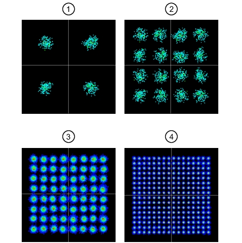
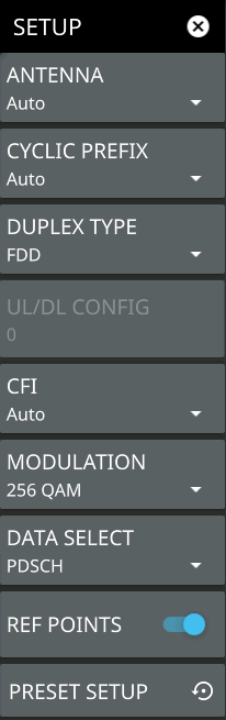
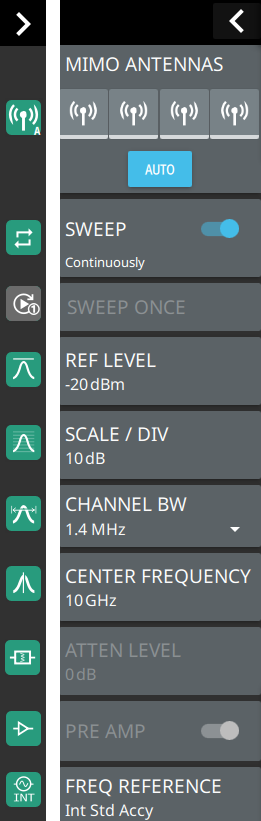
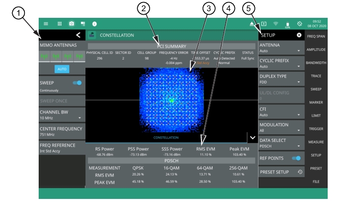
1. LTE Analyzer Status Panel: Each measurement features a unique status panel that displays settings and information relevant to the current measurement and view settings. This panel provides quick access to the MIMO antenna selection and status, sweep setting, and channel bandwidth and frequency configuration. See Status Panel (LTE Constellation).
2. PCI SUMMARY: This area shows the physical cell ID, including the sector ID, cell group number, frequency error, time offset, cyclic prefix, and sync status. Sync status can indicate if there is a PSS or SSS failure, a Full Sync, or an Unknown condition. Also noted is the instrument’s reference clock accuracy of Internal, External, or GNSS (GPS) high accuracy (requires GPS).
3. Constellation: This area displays the demodulated symbol point location on an IQ coordinate plot. Points are drawn in colors that are associated with the symbol point density. Warmer colors (red/orange) indicate a higher symbol density where cooler colors (cyan/blue) indicate lower symbol density. The ideal symbol reference point location overlay can be toggled on or off via the SETUP menu.
4. POWER: Shows power levels in dBm of each physical layer control:
Reference Signal (RS) Power: The reference signal is used for downlink channel estimation.
Primary Synchronization Signal (PSS) Power. The primary sync signal is used to obtain slot synchronization. It contains information needed for cell search.
Secondary Synchronization Signal (SSS) Power: The secondary sync signal is used to obtain frame synchronization and cell identity. It contains information needed for cell search.
Error Vector Magnitude (EVM): RMS and PEAK EVM are shown for each demodulated format (QPSK, 16-QAM, 64-QAM, 256-QAM), including the total RMS EVM and PEAK EVM for the measurement at the top of the table.
5. SETUP Menu: The constellation measurement settings are configured in the SETUP menu. See SETUP Menu (LTE Constellation).
Figure: LTE Constellation Measurement Examples illustrates example LTE constellation diagrams. The examples are presented with the reference point overlay enabled for the specific modulation type. A tighter grouping of points generally means a better quality signal with fewer symbol errors. Also, the point color indicates the relative symbol density at that location. Red, orange and yellow points represent a higher symbol count and green, cyan, and blue represent a lower symbol count.
LTE Constellation Measurement Examples 
1. Over-the-air QPSK measurement.
2. Over-the-air 16-QAM measurement.
3. Conducted 64-QAM measurement.
4. Conducted 256-QAM measurement.
Note 
The reference point overlay is displayed individually when the modulation format is selected (QPSK, 16-QAM, 64-QAM, or 256-QAM). When the modulation format is set to All, then all modulation reference points are shown. Each modulation format reference point is color coded. These colors do not match the display point colors.
 
SETUP Menu (LTE Constellation)
The constellation SETUP menu is available in MEASURE > MEASUREMENT > Constellation > SETUP.
SETUP Menu (LTE Constellation)
-
 
ANTENNA
Sets the MIMO antenna number (0 to 3, or AUTO) to use during a measurement. AUTO will use the antenna with the highest received signal power.
CYCLIC PREFIX
Sets the cyclic prefix (or guard time interval) to Normal, Extended, or Auto. The cyclic prefix is a duplication of a fraction of the symbol end. This setting affects the OFDM symbol sensitivity to time dispersion.
DUPLEX TYPE
Selects either frequency division duplex (FDD) or time division duplex (TDD).
UL/DL CONFIG
Available only in TDD duplex type. Sets the uplink/downlink (UL/DL) configuration, or Frame Format. This selection determines which sub-frames are uplink sub-frames and which are downlink sub-frames, and where the transitions between uplink and downlink sub-frames occur.
CFI
Selects the control format indicator (CFI) which indicates how many OFDM symbols are used for carrying the control channel at each sub-frame. CFI1 uses the first symbol at the sub-frame for PDCCH allocation. CFI2 uses the first and the second symbol for PDCCH. CFI3 uses the first three symbols for PDCCH.
MODULATION
Selects the modulation format (ALL, QPSK, 16-QAM, 64-QAM, 256-QAM). When the data format is set to PBCH, only QPSK is available.
DATA SELECT
Selects the data format of Physical Downlink Shared Channel (PDSCH) or Physical Broadcast Channel (PBCH).
REF POINTS
Toggles the ideal reference point locations on or off. Note that each modulation format reference point is color coded.
PRESET SETUP
Presets the SETUP menu to default settings.
 
Status Panel (LTE Constellation)
The status panel illustrated in this section is unique to the current analyzer and to the particular measurement and view that is selected.
Figure: Status Panel with Minimized Status Panel Icons (LTE Constellation) shows the LTE status panel with minimized status panel icons that covers the LTE constellation measurement.
Status Panel with Minimized Status Panel Icons (LTE Constellation) 
 
MIMO ANTENNAS: Toggles the current MIMO antenna setting between AUTO or to select one of the available antennas. When a single antenna is selected, a blue underscore will appear below the antenna icon. The antenna icon is highlighted green when receiving a signal.
SWEEP: Toggles the current sweep setting between continuously or sweep once.
SWEEP ONCE
When sweep is set to single sweep, SWEEP ONCE updates the measurement display. Data continues to be captured in the background.
REF LEVEL
Sets the reference level of the top graticule line in the selected units. If the reference level offset is not zero, OFFSET REF LEVEL is displayed at this location. Refer to Setting Amplitude.
SCALE/DIV
Sets the graticule scale/division for log-based units. This setting does not apply to linear units.
CHANNEL BW
Sets the measurement channel bandwidth. The available bandwidth settings depend on the selected band and bandwidth option installed in the instrument.
CENTER FREQUENCY
Sets the center frequency of the measurement channel.
ATTEN LEVEL
When auto attenuation is off, sets input attenuation.
PRE AMP
Toggles the low-noise front-end preamplifier on or off. Refer to Setting Amplitude.
FREQ REFERENCE
Indicates the current frequency reference source of Internal, External, or GNSS (GPS) Hi Accuracy (requires GPS). The instrument automatically selects the frequency reference in the following order of priority: external, GNSS (GPS), then the internal time base.