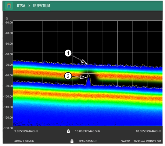
Real-Time Spectrum Analyzer (RTSA) Measurement Guide : Real-Time Spectrum Analyzer (Option 199) Overview : Setting Amplitude Parameters
 
Setting Amplitude Parameters
The amplitude scale corresponds to the y-axis display. The Real-time spectrum Analyzer supports log units such as dBm and dBV. Amplitude-related parameters are set using the AMPLITUDE Menu.
Setting Amplitude Units
This setting allows you to set the y-axis graticule units and applies to most of the spectrum analyzer measurements, including markers, traces, and limit lines.
1. Press AMPLITUDE > Y AXIS UNIT
2. Select the desired y-axis amplitude units from the following: dBm (default), dBV, dBW dBmV, dBµV, or dBA.
When switching amplitude units, the following parameters are affected as described below:
Reference level is converted directly from the current unit into the new unit and scaled appropriately.
The reference level offset is always entered in dB.
When changing from log units to log units, scaling (dB/div) remains unchanged.
Trace in a “HOLD / VIEW” mode will be scaled to match the newly selected units.
Marker amplitudes will be scaled to match the newly selected units.
Limit line points will be directly converted and displayed in the newly selected amplitude units.
Trigger levels will be converted to the newly selected units.
Measurements and setups will be converted to the newly selected units.
Save and recall will retain the units configuration.
Power cycle will retain the current units configuration.
Setting Amplitude Reference Level
The amplitude reference level is typically an absolute reference level set at the top of the graticule for the power level being measured. Signal levels above this set value will be outside of the display range and may overdrive and saturate the input circuit (refer to Indications of Excessive Signal Level). To set the current amplitude reference level:
1. To automatically set an optimum reference level, press AMPLITUDE > AUTO REF LEVEL.
2. To manually set the reference level, press AMPLITUDE > REF LEVEL, then enter the desired reference level.
Note 
Select AUTO ATTEN coupling of the attenuator setting and AUTO REF LEVEL to help ensure that harmonics and spurs are not introduced into the measurements.
Setting Amplitude Range and Scale
This setting applies to most analyzer modes of operation and allows you to set the y-axis graticule scale for log-based units only.
1. Press AMPLITUDE > SCALE/DIV.
2. Enter the desired number of units per division.
Reference Level Offset for External Loss or External Gain
To obtain accurate measurements, you can compensate for any external attenuation or gain by using a reference level offset. The compensation factor is always in dB, even if linear amplitude units are selected. External attenuation can be created by using an external cable or an external high power attenuator. External gain is typically from an amplifier.
To adjust the reference or amplitude level for either gain or loss:
1. Press AMPLITUDE > REF LEVEL OFFSET.
2. Enter a positive dB value to account for gain or enter a negative dB value to account for loss.
3. The new reference level offset value will be displayed on the instrument and the y-axis and trace amplitude is adjusted accordingly.
Attenuator Functions
The spectrum analyzer includes a step attenuator at the RF input. This attenuator is used to reduce large signals to levels that make best use of the analyzer’s dynamic range. By default, the auto attenuation automatically adjusts the attenuator as a function of the reference level. In the AMPLITUDE menu, the ATTEN LEVEL allows manual adjustment of the input attenuation. When auto attenuation is selected, both the reference level and the attenuation are increased. The following actions, listed in decreasing order of effectiveness, can facilitate the detection of low-level CW signals:
Decrease the reference level and attenuation. Refer to AMPLITUDE Menu.
Turn on the preamplifier.
Reduce RBW. Refer to Setting Bandwidth Parameters.
Preamplifier
The preamplifier can be turned on and off by toggling PRE AMP via the status panel or the AMPLITUDE menu. Figure: 1. Preamplifier Off 2. Preamplifier On shows the noise floor with the preamplifier off (1) and on (2). Note that when the preamplifier is turned on, the noise floor drops significantly and a low-level signal is exposed. In order to use the preamplifier, the attenuation must be lower than 20 dB. If the preamplifier is turned on when the attenuation is greater than or equal to 20 dB, the attenuation will automatically drop to 10 dB. When AUTO ATTEN is toggled on, the REF LEVEL must be set to –40 dBm or lower to enable the preamplifier.
1. Preamplifier Off
2. Preamplifier On
Indications of Excessive Signal Level
The instrument has built-in features to help prevent input overload. These include auto attenuation and reference level. The instrument will also indicate when a received signal is too high for the current setup by displaying an “ADC Overrange” notification in the title bar (Figure: ADC Overrange). Before proceeding with the measurements, adjust the reference level, the attenuation level, and disable the preamplifier if necessary. Adjusting the resolution bandwidth and frequency range may also help when measuring small signals that are near large signals.
ADC Overrange
Overpower Warning
The Field Master Series MS2080A/MS2070A and Site Master MS2089A instruments are equipped with an in-built overpower protection hardware in order to manage considerably high range of input power. If the input power range exceeds beyond 5 watts, the protection relay gets activated and a notification alert is displayed as shown in the Figure: Overpower Warning. Proceed by removing the high power input source to avoid to damaging the RF circuitry.
 
Overpower Warning
 
AMPLITUDE Menu
 
AMPLITUDE Menu
 
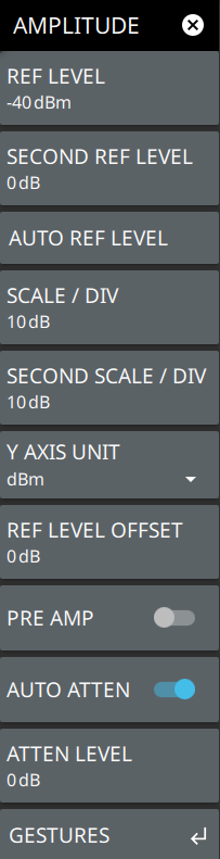
REF LEVEL
The reference level is the top graticule line on the measurement display. If the reference level offset is not zero, the offset reference level is displayed at this location. Pressing the plus (+) or minus (–) control increments the value by 10. The plus/minus (+/-) button on the keypad toggles between positive and negative values.
SECOND REF LEVEL
The reference level is the top graticule line to the right on the measurement display. Its functionality is exactly same as reference level, but it is only available when trace math is enabled.
AUTO REF LEVEL
Auto reference level automatically adjusts the reference level to place the highest signal amplitude at about two graticule lines from the top based on the position of the trace at the time the button is pressed.
SCALE/DIV
The scale can be set from 1 dB per division to 15 dB per division. The default setting is 10 dB. Pressing the plus (+) or minus (–) control changes the value by 1. SCALE/DIV is not available when linear y-axis amplitude units are selected.
SECOND SCALE/DIV
It applies to second reference level and is available only when trace math is enabled.
Y AXIS UNIT
Selects the y-axis amplitude units. Available units are: dBm, dBW, or dBV, dBmV, dBµV, dBA.
REF LEVEL OFFSET
Reference level offset compensates for the presence of external input attenuation or gain. The offset is applied to all amplitude related parameters and to measurements such as the y-axis scale and marker measurements. The default offset value is 0 dB and will always be presented in dB units. Pressing the plus (+) or minus (–) control increments the value by 10. The plus/minus (+/-) button on the keypad toggles between positive and negative values. Refer to Reference Level Offset for External Loss or External Gain.
PRE AMP
Turns the low-noise front-end preamplifier on or off. To ensure accurate measurement results, the largest signal into the instrument input when the preamplifier is turned on should be less than –40 dBm. The preamplifier cannot be turned on if auto attenuation is on and the reference level is above –40 dBm. Refer to Preamplifier.
AUTO ATTEN
Input attenuation can be either tied to the reference level (on) or manually selected (off). When input attenuation is tied to the reference level, attenuation is increased as higher reference levels are selected to make sure the instrument input circuits are not saturated by large signals that are likely to be present when high reference levels are required.
ATTEN LEVEL
When auto attenuation is off, the attenuation value can be set manually to a resolution of 5 dB. Pressing the plus (+) or minus (–) control increments the value by 10.
GESTURES
Press GESTURES to lock the reference level by toggling the DRAG button on/off.