Limit lines allow you to monitor when trace data crosses a defined line. Two types of limit lines can be specified: lower limit lines and upper limit lines. Limit lines can be used for visual reference, pass/fail criteria, and to trigger a save on event. By using save on event, a signal that crosses a limit line can be automatically saved (refer to Saving and Recalling Measurements).
Each limit line can consist of a single segment, or as many as 40 segments across the entire frequency span of the instrument. These limit segments are retained regardless of the current frequency span of the instrument, which allows the configuring of specific limit envelopes at various frequencies of interest without having to re-configure them each time the frequency is changed. Limit line parameters are set using the LIMIT Menu.
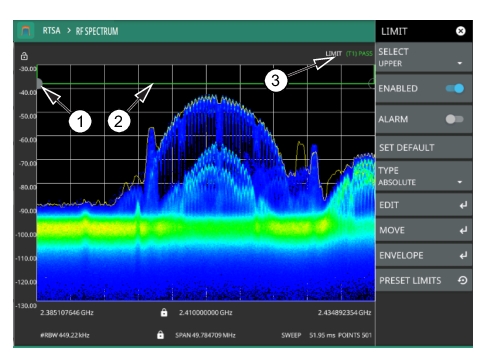
Simple Limit Line
1. Limit points are shown as gray circles. The active point is filled in gray. Points can be dragged into position or set discretely using the frequency and amplitude settings in the LIMIT EDIT Menu.
2. The limit line shown here is a simple upper limit line. The limit line color is green when the trace does not cross the limit line, and the limit line color turns red when the trace crosses it.
3. The limit test pass/fail status is also shown in green or red color at the top of the display. The limit test is applied to the active trace, indicated here by T1.
Simple Limit Line
1. Press LIMIT on the main menu.
2. Select UPPER or LOWER limit.
3. Toggle the selected limit line on using the ENABLED toggle.
4. To change the frequency or amplitude level of the limit line:
b. Enter either an X-OFFSET frequency value or Y-OFFSET amplitude value.
c. Press LEFT, RIGHT, UP, or DOWN to move the limit line the by the value entered above.
You can set up either an upper or lower limit line, or both by repeating the procedure above.
Limit Line Envelope
Limit line envelope parameters are set using the LIMIT ENVELOPE Menu. The limit line envelope feature is a quick way to generate an envelope using the existing trace as a reference. You can set the envelope to square or slope and you can set the limit line offset from the trace when creating the envelope. Once the envelope limit line is set, you can manually edit the limit line by dragging the points or by using the LIMIT EDIT Menu and LIMIT MOVE Menu.
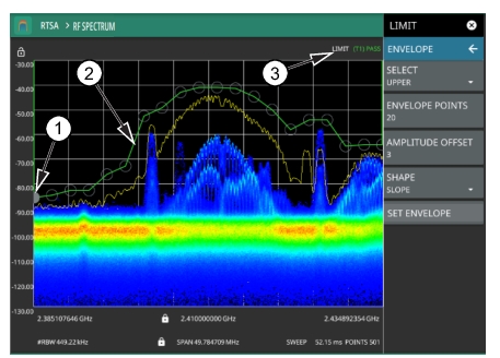
Envelope Limit Line
1. Limit points are shown as gray circles. The active point is filled in gray. Points can be dragged into position or set discretely using the frequency and amplitude settings in the LIMIT EDIT Menu.
2. The limit line shown here is an upper envelope limit line. The limit line color is green when the trace does not cross the limit line, and the limit line color turns red when the trace crosses it.
3. The limit test pass/fail status is also shown in green or red color at the top of the display. The limit test is applied to the active trace, indicated here by T1.
To set up a limit line envelope:
1. Press LIMIT > ENVELOPE.
2. Select either Upper or Lower limit line.
3. Set the number of limit envelope points.
4. Set the amplitude offset.
5. Select the envelope shape of Square or Slope.
6. Press SET ENVELOPE to generate the limit line envelope.
You can set up either an upper or lower limit line, or both by repeating the procedure above. To create a more complex limit line, use the LIMIT EDIT Menu to work with individual limit line points.
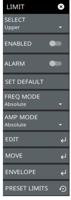
LIMIT Menu
LIMIT Menu
SELECT: Selects UPPER or LOWER limit line for editing.
ENABLED: Displays the selected limit when toggled on.
ALARM: This setting is for toggling the alarm function on or off for the currently active limit line. When on, an alarm beep will occur when a data point exceeds the limit. Audio functionality will be added via an upcoming software update.
SET DEFAULT: Pressing this button deletes all limit points for the currently active limit line and sets the default limit line value, which is a single limit whose position is 2.5 grid lines from the top of the screen (for the upper limit line) or 2.5 grid lines from the bottom of the screen (for the lower limit line), depending upon which limit is active. The inactive limit line is not altered.
FREQ MODE: Sets frequency mode of the selected limit line as absolute or relative. This selection may be used at any time while working with limit lines. Absolute limit lines set the limit inflection points based upon the entered frequencies for each point. Relative limit lines set the limit inflection points relative to the current center frequency. Regardless of how a limit line is set up, saved, or recalled, it can be changed between absolute and relative by pressing the desired state.
AMP MODE: Sets amplitude mode of the selected limit line as absolute or relative. This selection may be used at any time while working with limit lines. Absolute limit lines set the limit inflection points based upon the entered frequencies for each point. Relative limit lines set the limit inflection points relative to the current center frequency. Regardless of how a limit line is set up, saved, or recalled, it can be changed between absolute and relative by pressing the desired state.
PRESET LIMITS: Presets the limit lines to default values.
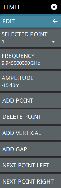
LIMIT EDIT Menu
LIMIT EDIT Menu
SELECTED POINT: Displays the limit line point number. Press to select a different point from the displayed list.
FREQUENCY: Sets the frequency of a limit line inflection point. The frequency of each point in a limit line can be individually set. When a new point is added, it takes the value that is halfway between two existing points, or it takes the stop frequency of the current sweep if no point is higher in frequency than the one being added. See the ADD POINT button description for more details. Use the keypad or the left and right arrow keys to change the frequency of an inflection point. The left or right arrows move the inflection point by ±0.1. Up or down arrows move the inflection point ±1.
AMPLITUDE: Sets the amplitude of a limit line inflection point. The amplitude of each inflection point can also be individually set. By default, when a new point is added it takes the amplitude value that is on the limit line at the frequency where the point was added. Use the keypad (using +/- to set a negative value) or the plus (+) or minus (–) control to increment the value. The unit of the amplitude limit is the same as the current vertical amplitude unit (for example, dBm).
ADD POINT: Press this button to add a limit line inflection point. The precise behavior of this button depends upon which inflection point is active at the time that the button is pressed. If the active limit point is somewhere in the middle of a multi-segment limit line, then a new limit point is added that is halfway between the currently active point and the point immediately to its right. The amplitude of the inflection point will be such that it falls on the limit line. For example, if a limit point exists at 2.0 GHz with an amplitude of –30 dBm, and if the next point is 3.0 GHz with an amplitude of –50 dBm, then the added point will be at 2.5 GHz with an amplitude of –40 dBm. If the last limit point is active (assuming it is not at the right edge of the display), then the new limit point will be placed at the right edge of the display at the same amplitude as the point immediately to its left. Points may not be added beyond the current sweep limits of the instrument. Use the FREQUENCY and AMPLITUDE buttons to make adjustments to the selected point.
DELETE POINT: Press this button to delete the selected point.
ADD VERTICAL: Press this button to add an inflection point below the currently selected point.
ADD GAP: Select this button to disconnect the continuous limit line. It can be used when you don’t want to apply limit to a specific portion of the trace.
NEXT POINT LEFT: Press this button to select the inflection point that is immediately to the left of the active point, making this newly selected point active for editing or deletion. With each button press, the active point becomes that point to the left of the previously active point, until the newly selected active point becomes the left-most point on the screen.
NEXT POINT RIGHT: Press this button to select the limit point immediately to the right of the active point, making this newly selected point active for editing or deletion. With each button press, the active point becomes that point to the right of the previously active point, until the newly selected active point becomes the right-most point on the screen.
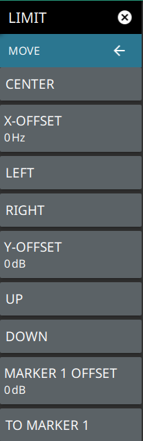
LIMIT MOVE Menu
LIMIT MOVE Menu
CENTER: Pressing this button moves the center of the existing limit line to the center frequency of the measurement. The span of the existing limit line is not changed. Use this button as an easy way to move an existing limit line to the center of the sweep. This button has no action if no limit line is turned on.
X-OFFSET: Allows you to adjust the frequency of the limit line. All inflection points will be moved by the value entered here when using the LEFT or RIGHT buttons. Press X-OFFSET and enter a value using the keypad.
LEFT: Pressing this button moves all inflection points to the left by the X-OFFSET value.
RIGHT: Pressing this button moves all inflection points to the right by the X-OFFSET value.
Y-OFFSET: Allows you to adjust the amplitude of the limit line. All inflection points will be moved by the value entered here when using the UP or DOWN buttons. Press Y-OFFSET and enter a value using the keypad.
UP: Pressing this button moves all inflection points up by the Y-OFFSET value.
DOWN: Pressing this button moves all inflection points down by the Y-OFFSET value.
MARKER 1 OFFSET: Sets a limit line offset value from Marker 1 amplitude. This feature moves the limit line amplitude and frequency as needed to place the center of the limit line the user-specified amplitude from the position of Marker 1. Positive values place the limit line above Marker 1, and negative values place the limit line below Marker 1.
TO MARKER 1: Moves the limit line center position to the frequency and specified amplitude offset of Marker 1. Marker 1 must be enabled.
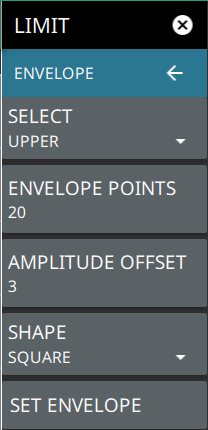
LIMIT ENVELOPE Menu
LIMIT ENVELOPE Menu
SELECT: Press this button to select UPPER or LOWER for envelope design.
ENVELOPE POINTS: This sets the desired number of envelope points.
AMPLITUDE OFFSET: Use to define how far away from the trace to place the upper or lower envelope. For an upper envelope, usually the offset will be positive in order to place the envelope above the signal. For a lower envelope, the offset will usually be negative in order to place the envelope below the signal.
SHAPE: Use to choose whether the upper or lower envelope will be with flat tops (SQUARE setting) and vertical lines, or whether the envelope will have sloped lines (SLOPE setting) between adjacent inflection points. When the square envelope type is selected, two inflection points are used for each horizontal segment.
SET ENVELOPE: Press this button to generate the envelope using the set characteristics. If the default results are not satisfactory, you can make adjustments to the amplitude and frequency of each inflection point, and you can add or delete inflection points.