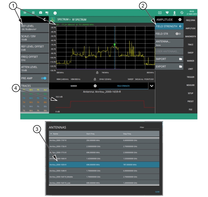
The field strength measurement is selected using the RF Spectrum mode. The field strength measurement is used in conjunction with an Anritsu antenna that has known antenna factors. Users can also import custom antenna factors for antennas not listed in the standard antenna selection list. When the field strength measurement is enabled, an additional plot is shown at the bottom of the display, indicating the selected antenna factor over the currently set frequency span. The field strength measurement is a measure of the RF power density that automatically compensates for the selected antenna factor. If an antenna is not selected, then the antenna gain is assumed to be 0 dB over the entire measurement range and the measurement can be manually compensated for using the Antenna Calculations, or to otherwise convert from one unit of measure to another.
Field Strength Measurement
1. When the field strength measurement is enabled (2), all amplitude units are converted to display field strength in the selected units.
2. The field strength measurement and antenna is selected from the AMPLITUDE menu.
3. The ANTENNAS dialog is displayed when ANTENNA is selected from the FIELD STRENGTH menu (2).
4. The antenna factor profile (in dB) is plotted across the currently set sweep range for the selected antenna.
Frequency and level settings for many interfering signals can be set as follows:
1. Set up the measurement frequency and bandwidth.
2. Select the AMPLITIDE and set up the amplitude parameters.
3. Select the FIELD STRENGTH button and enable FIELD STR.
4. Select the ANTENNA button and select the antenna being used for the measurement.
Field strength is a constant measurement; after it is turned on, it remains on until FIELD STR is toggled off.
AMPLITUDE FIELD STRENGTH Menu
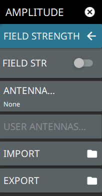
The FIELD STRENGTH menu is available in AMPLITUDE > FIELD STRENGTH. Once the field strength measurement is enabled, the FIELD STRENGTH menu can be quickly accessed by tapping on the Antenna factor display area below the spectrum window.
FIELD STRENGTH Menu
FIELD STR
Toggles the field strength measurement on or off. When toggled on, the trace detector type is set to RMS/Avg and the antenna factor profile is displayed.
Displays a list of user antennas. User antenna files are imported as comma separated value files. The file can contain multiple antennas and must conform to the following:
• Each antenna name must be unique, contain alpha-numeric characters only, and must be on a single line.
• Frequency must be in MHz.
• Antenna factors must be in dB.
IMPORT
Imports a user antenna file (.csv).
EXPORT
Exports a user antenna data file (.csv). If none exist, exports an example user antenna data file with instructions on how to create a usable antenna data file.
Example User Antenna Data
To create a list of custom antenna factors, use the following steps:
1. Export the existing USER ANTENNAS csv file by pressing the EXPORT button in the FIELD STRENGTH menu.
2. From the FILES menu, move the exported file to a USB memory device and then to a computer for editing.
3. If this is the first time exporting the file, read the instructions at the top of the file, then delete those rows:
**
This is an EXAMPLE. Make sure to REPLACE and DELETE all existing content in this file, including these instructions.
Accepted criteria:
Each Antenna name must be unique, contain alpha-numeric characters only, and must be on a single line
Frequency must be in MHz
Factors must be in dB
Please use the following examples as a guide:
**
4. Name each custom antenna and add cal factors below, per the instructions in the header:
Antenna_Example1
1920 35.886
1930 35.931
1940 35.976
1950 36.021
1960 36.065
1970 36.109
1980 36.153
Antenna_Example2
2110 36.706
2120 36.747
2130 36.788
2140 36.828
2150 36.869
2160 36.909
2170 36.949
5. Save the file to a USB memory device and insert it into the instrument.
6. Select the IMPORT button in the FIELD STRENGTH menu and select the new file from the USB drive.
7. Select USER ANTENNAS… button to view the list of imported antennas.
Antenna Calculations
This section provides a list of various antenna calculations to convert from one unit of measure to another.
AF = antenna factor, ratio of incident electromagnetic field to the output voltage
Ae = antenna equivalent area
g = antenna gain as power ratio
G = antenna gain in dBi
C0 = speed of light in vacuum, 299,792,458 m/s
Equations
P = V2/R
VdBµV = PdBm + 107 dB
Ae = g(λ2/4π)
G = 10*log(g)
g = 10G/10 = (9.73/λ10AF/20)2
ƒ = C0/λ
Pr = AePd
Pd = PtGt/(4πr2) (Power density at a point)
Pd = E2/Z0 = E2/120π = Z0H2
E = Z0H = √(Pd120π)
AF = 20*log(9.73/λ√g)
The field strength equations are only valid in the far field, where electric and magnetic fields are related by the characteristic impedance of free space.