Cable and Antenna Analyzer Measurement Guide : Cable and Antenna Analyzer Measurements : Setting Up Markers
 
Setting Up Markers
Markers can be applied to active or recalled measurements. The instrument supports eight markers. Marker information is stored in measurement and setup files and is displayed when either file type is recalled. Selecting MARKER on the main menu will bring up the marker functions.
Overview of Markers
Frequency measurements (Return Loss, Cable Loss, VSWR, and Smith Chart, and Transmission (USB Sen)) have common markers. Distance measurements (DTF Return Loss and DTF VSWR) also have common markers.
The active marker data is displayed at the top of the measurement scale and indicates the trace to which the marker is attached (i.e., T(1) for trace 1).
The active marker has a solid fill and is highlighted in the marker table. The vertical blue line is also placed on the active marker (excluding Smith Chart) and can be used to drag the markers position.
To move a marker, press the marker line and drag. For Smith Chart, use the + and buttons below the chart to increment the marker location up or down. To set a more exact location, use the MARKER menu to set a specific frequency or distance value.
Markers set beyond the current frequency or distance range are displayed at either the left or right of the trace window with an arrow.
Marker location and type are stored after the marker is turned off.
PRESET MARKERS restores the markers to their default state. All markers are turned off and previous marker information is not saved.
Markers 1, 2, and 3 (Marker 3 is Out of Range)
Select, Activate, and Place a Marker / Delta Marker
1. Select MARKER on the main menu. Select a marker by pressing SELECT, then press one of the marker numbers to make it active.
2. Select ENABLED to toggle the marker on or off.
3. Select FREQUENCY or DISTANCE to edit the marker location, or drag the marker on the display. Figure: Delta Markers 1 and 2 shows a marker on the Smith chart, where the location can be changed by using the + or buttons, or by editing the frequency value.
4. Markers 2 through 8 can be set as a delta marker to the reference marker 1. Select MODE to select the active marker type as a Delta marker. Figure: Delta Markers 1 and 2 illustrates a delta marker between two return loss valleys.
Markers on Smith Chart (use the + or – buttons to move the marker location in increments)
Delta Markers 1 and 2
Marker Table
The Marker Table displays at the bottom of the measurement area. The table lists marker frequency/distance and amplitude information for all currently active markers.
To display the marker table, press MARKER on the main menu, then toggle MARKER TABLE on or off. The active marker is indicated with a blue background as shown in Figure: Delta Marker 2 and Marker Table.
Delta Marker 2 and Marker Table
Marker Search
All the cable & antenna measurements include markers that will find trace peak or trace valley automatically. Marker search in Smith Chart finds the lowest or highest j magnitude when searching for valley or peak, respectively.
1. Select MARKER on the main menu, then press SELECT and press a desired marker number.
2. Select MARKER SEARCH to open the MARKER SEARCH menu.
3. Select PEAK to set the marker to the peak of the measurement or press VALLEY to set the marker to the valley of the measurement.
Tracking Markers
A tracking marker is set to a peak or to a valley. As the peak (or valley) varies in the measurement trace, the tracking marker stays at the peak (or valley).
Any marker can be set to tracking from the MARKER main menu by toggling TRACK MARKER on, then use the MARKER SEARCH and select PEAK or VALLEY.
Marker to Memory
The marker to memory requires a trace first be saved to memory. Toggling marker to memory on places the active marker on the trace memory at the current location. Refer to Setting Trace Parameters for more details about setting up traces and trace memory functions.
Figure: Delta Marker 2 with Marker to Memory shows a return loss antenna measurement with an earlier trace saved to memory shown with the active trace. Markers 1 and 2 are enabled with Marker 2 set as a delta marker and toggled to memory. Both markers were set to search for the valley.
Delta Marker 2 with Marker to Memory
MARKER Menu
MARKER Menu
 
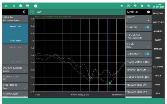
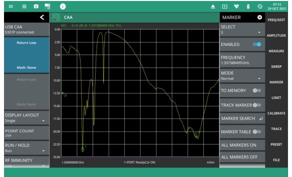
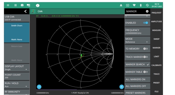
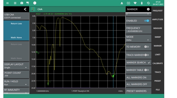
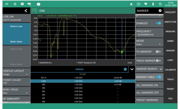
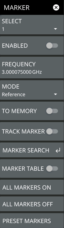
SELECT
Selects one of eight potential markers and makes it the active marker. You can also make a marker active by touching the vertical marker line.
ENABLED:
Toggles the display of the currently active marker on and off. When off, the location of the marker is stored.
FREQUENCY or DISTANCE
Displays the marker frequency (or distance for a DTF measurement). For delta markers, the frequency/distance is relative to the reference marker (Marker 1). Change the marker frequency by dragging it to the desired location (or use the +/- buttons for smith chart). You can also change the marker frequency or distance from the FREQ/DIST menu and change it manually using the keypad.
MODE
Sets the current active marker as a normal marker or a delta marker to Marker 1. Marker 1 is always the reference marker.
TO MEMORY
Toggles the marker to memory on or off. This sends the marker to the trace memory, so a trace must be saved to memory before toggling this on.
TRACK MARKER
When toggled on, the active marker becomes a tracking marker and defaults to tracking the valleys or peaks. The search settings cannot all be applied to a marker with tracking either on or off.
MARKER SEARCH
MARKER TABLE
Toggles on or off the marker table displayed below the measurement. Refer to
ALL MARKERS ON
Turns all markers on with either default values or previously set values if the markers have not been preset.
ALL MARKERS OFF
Turns all markers off, but markers will retain their last frequency position once re-enabled.
PRESET MARKERS:
Presets marker selections to default values.
MARKER SEARCH Menu
MARKER SEARCH Menu
 
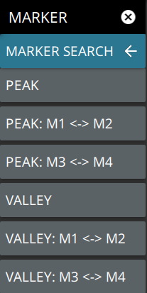
PEAK
Places the currently active marker on the highest signal amplitude currently displayed on screen.
VALLEY
Places the currently active marker on the lowest signal amplitude currently displayed on screen.
Markers 5, 6, 7, and 8 can perform a special Marker search to find the Peak or Valley between two other markers.

When Marker 5 or Marker 7 is Active
 
Peak Between M1 & M2: Places Marker 5 or 7 on the highest signal amplitude between Marker 1 and Marker 2.
Valley Between M1 & M2: Places Marker 5 or 7 on the lowest signal amplitude between Marker 1 and Marker 2.
When Marker 6 or Marker 8 is Active
 
Peak Between M3 & M4: Places Marker 6 or 8 on the highest signal amplitude between Marker 3 and Marker 4.
Valley Between M3 & M4: Places Marker 6 or 8 on the lowest signal amplitude between Marker 3 and Marker 4.