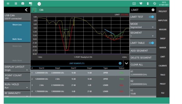
Cable and Antenna Analyzer Measurement Guide : Cable and Antenna Analyzer Measurements : Setting Up Limit Lines
 
Setting Up Limit Lines
Limit lines are used for visual reference or for pass/fail criteria using the limit alarm and pass/fail message settings. Selecting the LIMIT on the main menu displays the LIMIT menu.
Overview of limit lines:
Each measurement has a unique limit line.
The color of the limit line changes to red when a measurement trace exceeds a limit and when LIMIT TEST is enabled, the limit pass/fail result is displayed in the upper right of the measurement data.
Limits set beyond the current amplitude range are displayed at either the top or bottom of the graticule.
The limit line amplitude is stored when a limit line is turned off.
Limit lines must either be all single limit lines or all segmented limit lines. They cannot be mixed, but you can have a single segment as upper or lower limit lines.
PRESET LIMITS will turn off the limit line display, limit alarm and Pass/Fail message, and reset upper and lower limits to their default values.
Single Limit Lines
To enable a simple upper or lower limit lines:
1. Select LIMIT on the main menu.
2. Toggle UPPER LIMIT or LOWER LIMIT on or off.
3. Select UPPER LEVEL or LOWER LEVEL to edit the limit line amplitude, or use the touch screen to drag the limit line up or down.
A single limit line extends over the entire displayed range of the sweep, independent of the start/stop settings of the sweep. For a single limit line, the amplitude for the start/stop points is the same. Upper limit lines are labeled with a “UL”, and lower limit lines are labeled with an “LL”. Limit lines are displayed in green so long as the limits are not reached or exceeded. When a limit is exceeded (upper or lower), the limit line or segment turns red. Any portion of the measurement trace touching or exceeding a limit also turns red, while portions of the trace within limits remain in the default yellow color.
Figure: Single Limit Lines shows single upper and lower limit lines with the lower limit failing the limit test.
Single Limit Lines
Segmented Limit Lines
Segmented limit lines need not be continuous or connected as a single limit line. If any of the segments fail the limit test, the entire upper or lower limit fails the test. Additionally, segments can be added in any order and are not necessarily sequential from left to right or as all upper or all lower in sequence (i.e., segment 1 and 10 can be upper limits.
To enable segmented limit lines:
1. Select LIMIT on the main menu.
2. Select MODE and select Segmented. The segmented LIMIT menu will be shown (use the MODE selection to change between single or segmented limits).
3. Select SEGMENT TYPE and select Upper or Lower.
4. Toggle UPPER LIMIT or LOWER LIMIT on or off.
A single limit line segment is placed over the entire displayed range of the sweep, independent of the start/stop settings of the sweep. A segmented limit line can be divided into connected or disconnected segments with different start/stop frequency values (X1/X2) and corresponding start/stop amplitude values (Y1/Y2).
5. Select SEGMENT and select a segment number and make it the active segment. The active segment is shown in blue color.
6. Select X1 to set the start frequency of the active segment.
7. Select Y1 to set the start amplitude of the active segment.
8. Select X2 to set the stop frequency of the active segment.
9. Select Y2 to set the stop amplitude of the active segment.
Note 
Limit lines segments cannot be moved by using the touch screen.
Figure: Single Segment Limit Line shows a single segment limit line.
Single Segment Limit Line
10. Select ADD SEGMENT to add a new segment, then press SEGMENT TYPE to set it as an Upper or Lower segment.
A new segment is added after the currently set active segment and existing segment numbers are incremented by 1. The new segment starts from the stop point of the previous segment and ends at the start point of the next segment of the same type (upper or lower), or to the end of the sweep range if there are no following segments. Figure: Single Segment Limit Line shows three upper segments where the active segment 2 was added by making segment 1 active, then pressing ADD SEGMENT. The new segment was added and connects the end point of segment 1 and start point of segment 3.
Single Segment Limit Line
Segments are added, set as upper and lower, and their start and stop points are edited to create a complex pass/fail limit test. Figure: Single Segment Limit Line shows several upper and lower segmented limit lines with the lower limit failing.
Complex Segmented Limit Lines
Limit Table
A limit table can be displayed for segmented limit lines by toggling LIMIT TABLE on or off. The limit table is useful when creating very complex limit lines as you can directly select the limit segment to make it active and edit any of its parameters (start and stop points and its type) right from the table. Figure: Limit Table shows segmented limit lines with the limit table enabled. The lower segment is failing the limit test.
Limit Table
Limit Alarm
Select the LIMIT > ALARM to toggle the audible limit test alarm on or off.
LIMIT Menu (Single)
LIMIT Menu (Single)
 
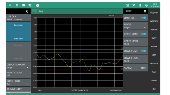
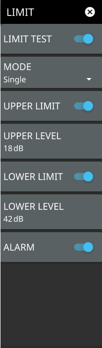
LIMIT TEST
When toggled on, a Pass or Fail message is displayed to indicate whether the trace touches or exceeds the limit line (Fail).
MODE
Sets the limit line to single or segmented. A single limit line will be set to a single threshold level. If using segmented limit lines, See LIMIT Menu (Segmented).
UPPER LIMIT
Toggles the upper limit line on or off.
UPPER LEVEL
Sets the amplitude of the upper limit line.
LOWER LIMIT
Toggles the lower limit line on or off.
LOWER LEVEL
Sets the amplitude of the lower limit line.
ALARM
When toggled on, an audible alarm sounds a repeating beep when the trace touches the limit line.
 
LIMIT Menu (Segmented)
 
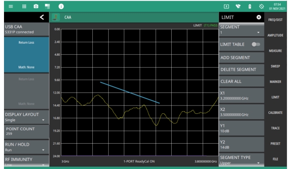
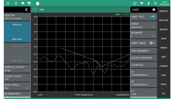
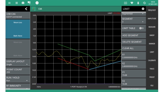
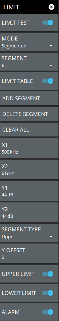
LIMIT TEST
When toggled on, a PASS or FAIL message is displayed at the top of the scale to indicate whether the trace touches or exceeds the limit line (FAIL).
MODE
Sets the limit line to single or segmented. Limit line segments are independent of each other and are defined by a start point and an end point. A maximum of 42 limit line segments can be defined. Both the upper and lower limit line segments for a measurement trace must be of the same type: either both are single, or both are segmented; however, you can create just one limit line segment as upper or lower to cover the entire measurement. If using single limit lines, see LIMIT Menu (Single).
SEGMENT
Selects one of the limit line segments and makes it active. An active segment appears blue in color.
LIMIT TABLE
Toggle on or off the limit table displayed below the screen. The limit table is only available when segmented limit lines are used. The limit table provides an easy to use interface for editing limit line segments. You can touch any segments X1, X2, Y1, Y1, or Refer to
ADD SEGMENT
Adds a limit line segment after the current active segment. All segment numbers after the current active segment will be incremented.
DELETE SEGMENT
Deletes the currently active segment. All segment numbers after the current active segment will be decremented.
CLEAR ALL
Removes all segments and does not store any segment information.
X1
Edits the start X value (frequency or distance) of the active limit line segment.
X2
Edits the stop X value (frequency or distance) of the active limit line segment.
Y1
Edits the start Y value (amplitude or phase) of the active limit line segment.
Y2
Edits the stop Y value (amplitude or phase) of the active limit line segment.
SEGMENT TYPE
Toggles the active limit line segment to upper or lower limit.
Y OFFSET
Applies an amplitude offset to all upper limit line segments. The offset value must not offset any upper limit line segments outside of the full scale amplitude for the measurement.
UPPER LIMIT
Toggles all of the upper limit line segments on or off.
LOWER LIMIT
Toggles all of the lower limit line segments on or off.
ALARM
When toggled on, an audible alarm sounds a repeating beep when the trace touches the limit line.