The number of data points determines the number of display points in the trace that are generated from the measurement data. The data points can be user defined. The range is between 2 and 16,001 for both Standard and Flex calibrations.
The snap data points ensure that all points in the sweep are calibration measurement points rather than interpolated points. The data point can be changed with the calibration enabled, but it will always snap to the nearest calibrated data point. The Start/Stop frequencies cannot be changed when the calibration is started.
Once the calibration is complete, the unit will return to the data point and Start/Stop frequencies that were in place at the start of the cal. The number of points and Start/Stop frequencies can be changed with the calibration enabled, with each frequency point being interpolated from the flex cal.
The default data point setting is 1000. This is recommended for most measurements. Increasing the data point increases the resolution of the measurement but slows down the sweep speed. The increased resolution can be helpful in DTF, as it enables increased distance coverage for the same distance resolution.
1. Select SWEEP on the main menu to open the SWEEP Menu.
2. Select DATA POINTS and enter the desired number using the numeric keypad.
RUN/HOLD
RUN/HOLD is used to start and stop line sweeping. When in hold mode, the RF output can be set on or off.
1. Select SWEEP menu from main menu to open the SWEEP Menu.
2. Select RUN/HOLD submenu to set the sweep either in Run or Hold mode.
3. When in Hold mode, toggle the HOLD RF MODE to enable or disable the RF output.
SWEEP TRIGGER
Sweep Trigger sets the VNA sweep mode to single or continuous. In single sweep mode, each sweep is initiated by SWEEP ONCE submenu.
1. Select SWEEP on the main menu to open the SWEEP Menu.
2. Select SWEEP TRIGGER and select Single or Continuous.
3. When in single sweep mode, press SWEEP ONCE to start one line sweep.
SWEEP TYPE
Vector Network Analyzers use different sweeping techniques to measure the characteristics of DUTs. Two common methods are linear sweep and segmented sweep.
A linear sweep involves measuring the S-parameters of a DUT across a specified frequency range in a continuous manner. The frequency is incremented in equal steps (linear increments) throughout the sweep.
A segmented sweep allows the user to define specific frequency segments of interest within a broader frequency range. The VNA measures only these segments rather than performing a continuous sweep across the entire range. Site Master VNA mode supports Frequency-Based Segmented Sweep
In many applications, having a simple list of frequencies where the step size between points is uniform is not adequate. The DUT specifications may have specifications in certain bands and certain specific frequencies that must be tested, there may be certain communications bands that must be tested, or there may be certain spot frequencies that are of interest for troubleshooting or analysis.
For these cases and others, segmented sweep allows one to put together a very arbitrary list of frequencies to sweep as well as having some control of instrument behavior that is distinct at these different points and/or segments. The entire sweep is broken into segments (a segment may contain one or many points) and in each segment, one can independently control the following:
• IF bandwidth
• Sweep Averaging
• Port 1 Power
The frequency of the segments is always monotonically increasing (within a segment and between segments). Plotting is based on the frequency of the particular point. Using segmented frequency-based sweep you can create multiple linear segments each with its own independent start and end frequencies.
1. Select SWEEP on the main menu to open the SWEEP Menu.
2. Select SWEEP TYPE and select LINEAR or SEGMENTED. Refer SEGMENT SWEEP for detailed information about segmented sweep.
Note
USER CAL must be turned off to set the SWEEP TYPE to SEGMENTED.
RF Immunity
The RF Immunity setting provides a way to protect the instrument from stray signals generated by nearby or co-located transmitters that can affect measurements. Interfering signals can make the measurement look better or worse than it is. To improve the instrument’s ability to reject unwanted signals, you can set the RF immunity to high. However, sweep speed may be slowed as a result.
The RF immunity default setting is low, which makes the instrument more susceptible to interfering signals during a measurement, but optimizes sweep speed. This is appropriate when the instrument is used in an environment where RF noise is not of great concern.
1. Select SWEEP on the main menu to open the SWEEP Menu.
2. Select RF IMMUNITY and select either High or Low.
SWEEP Menu
Access SWEEP menu from main menu.
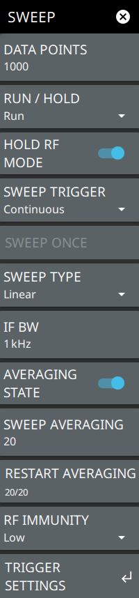
SWEEP Menu
DATA POINTS
Sets the number of data points to be included in the sweep. You can set any number of data points from 2 up to 16001. The larger the number of data points, the slower sweep speed. Data Points is disabled if sweep type is set to Segmented, but is available in SEGMENT SWEEP.
RUN/HOLD
Sets the sweep to either Run or Hold.
HOLD RF MODE
Toggles RF power transmitted from Port 1 when the instrument is put in Hold mode. The RF power can be set either to stay on or to be turned off during Hold. The default setting is for the RF to stay on during Hold, which helps to stabilize the instrument temperature.
SWEEP TRIGGER
Switches between single and continuous sweeping. Note that continuous is the default setting.
SWEEP ONCE
Gets enabled when the SWEEP TYPE is set to Single.
SWEEP TYPE
Selects the SWEEP TYPE as Linear or Segmented.
SEGMENT SWEEP
Opens SEGMENT SWEEP. A segmented sweep allows defining the number of data points used at each sweep segment. Adds frequency-based segments within the frequency range of the instrument.
IF BW
Sets intermediate frequency (IF) bandwidth. Select 10 Hz for the maximum dynamic range; select 100 kHz for the maximum speed. IFBW is disabled if sweep type is set to Segmented, but is available in SEGMENT SWEEP submenu.
AVERAGING STATE
Enables sweep averaging when toggled. Notice that the averaging state is included next to the graph type displayed on the top left corner of sweep window.
SWEEP AVERAGING
Sets the number of sweeps to be used for averaging.
RESTART AVERAGING
Restarts sweep averaging if AVERAGING STATE is turned on.
RF IMMUNITY
Sets the RF immunity to either low or high. By default, RF immunity is low. RF immunity is disabled if sweep type is set to Segmented.
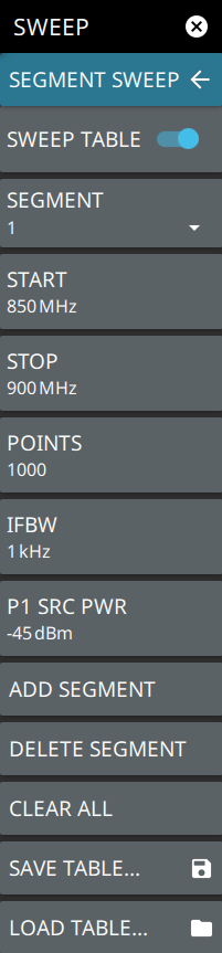
To access segment sweep go to main menu, SWEEP > SWEEP TYPE > Segmented > SEGMENT SWEEP. You can create frequency-based segmented sweeps to analyze a designated portion of the trace with specific number of data points, Port 1 source power and IFBW
SEGMENT SWEEP Submenu
SWEEP TABLE
Displays sweep segments table displayed under the VNA graph. Note that a table entry denoting the segment index of the active trace with full span is available by default.
SEGMENT
Selects one of the added segment, the default value is 1 and a maximum of 100 segments can be added.
START
Sets the start frequency of the segmented sweep within the frequency range of the instrument.
STOP
Sets the stop frequency of the segmented sweep within the frequency range of the instrument.
POINTS
Sets the number of data points. Minimum is 2 and maximum is 16,001 points.
IFBW
Sets the intermediate frequency (IF) bandwidth. Maximum is 1000 kHz and minimum is 0.01 kHz.
P1 SRC PWR
Sets port 1 source power.
ADD SEGMENT
Adds a new frequency-based segment at the end of the active segment or the given segment index. To add a segment make sure to set the stop frequency less than the maximum frequency range of the instrument.
DELETE SEGMENT
Deletes an active segment.
CLEAR ALL
Clears all the added segments except the default segment.
SAVE TABLE
Saves the sweep segment table. Segmented sweep tables are saved as segmented sweep file with.sgs extension.
LOAD TABLE
Loads the segment table (.sgs) saved either internally or on to external USB memory device.
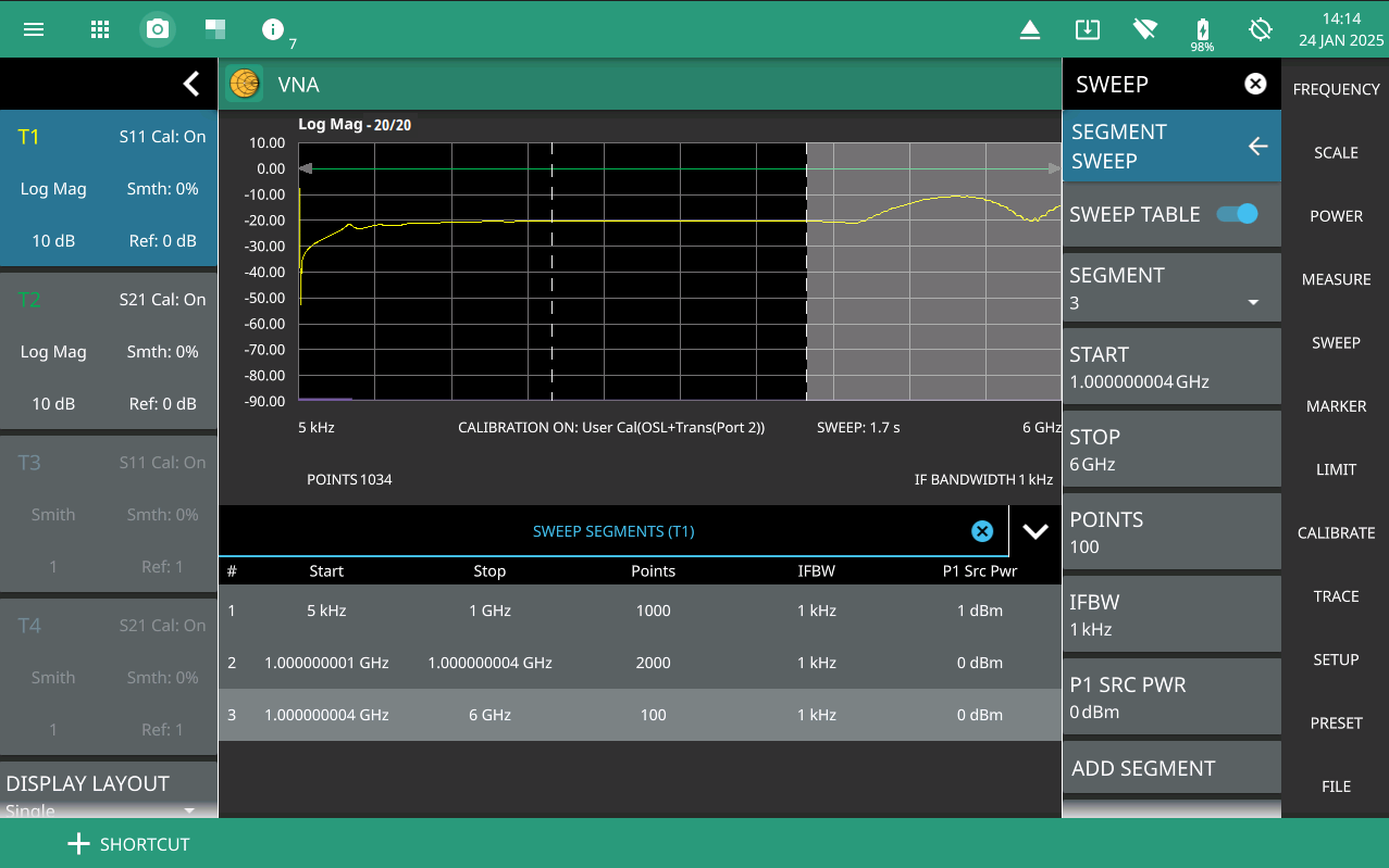
Adding Segmented Sweep
Segmented sweeps are multiple segments defined with different start and stop frequencies, along with varying number of points for each segment. Increase the number of data points to enhance the resolution and the dynamic range for the defined segments. By default, a segment covering the operating range of the instrument is available in the SWEEP SEGMENTS table displayed below the graph.
2. From SEGMENT SWEEP menu select STOP or simply touch the stop frequency of the segment listed in segment table, to set the stop frequency of the default segment below the operating range of the instrument.
3. Select ADD SEGMENT to add a new sweep segment.
A new segment is added after the default segment covering the full operating range of the instrument. The new segment starts with the stop frequency of the previous segment, incremented by 1 Hz and ends with the stop frequency incremented by 2 Hz. The active segment is highlighted by the shaded region as shown in Figure: Segmented Sweep.
4. Select DELETE SEGMENT to delete an unwanted segment.
Note
The default segment cannot be deleted. Once, the calibration is applied, the added segments cannot be deleted. To delete a segment, go to main menu, PRESET > PRESET MODE to disable the calibration.
5. Select SAVE TABLE to save sweep segments table as.sgs file.
6. Select LOAD TABLE to recall .sgs file saved in the instrument.
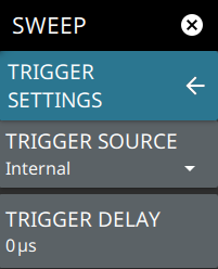
To access TRIGGER SETTINGS submenu go to main menu SWEEP > TRIGGER SETTINGS.
TRIGGER SETTINGS
TRIGGER SOURCE
Trigger source indicates whether or not to look for a trigger condition before making measurements. Sets the trigger source as one of the following:
• Internal: Internal trigger source performs continuous sweeping by default. But can be sweeped once if the SWEEP TRIGGER is set to Single.
• External Port 1: A TTL signal applied to the selected External Trigger SMA input connector causes a single sweep. After the sweep is complete, the resultant trace is continuously displayed until the next trigger signal is received.
• External Point Port 1: The external point trigger will enable a sweep to the next point. For example if there are 10 points, each trigger will trigger a sweep to the next point. The 11th trigger will sweep the 1st point.
TRIGGER DELAY
Sets the amount of time that the analyzer waits to begin a measurement after a trigger signal is received. Negative trigger delay effectively moves the trace to the right so you can observe the activity before the trigger event.