1. The status panel provides quick access to common VNA settings. Refer to VNA Display Overview.
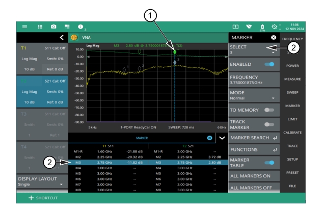
2. Marker located on trace. The active marker is indicated with solid green fill, other markers will show with a hollow fill, fixed markers show as a green X. The dashed vertical line is attached to the active marker and facilitates touch operations. Either the marker or the line can be dragged into position, and either can be double tapped to open a number of peak search options.
3. Selected marker in the MARKER menu and in the MARKER table. The marker table shows all of the marker parameters and measurement values. You can edit marker parameters from the marker table as well as from the MARKER menu.
Placing a Normal Marker
1. Select MARKER to display markers. If markers were off, Marker 1 will automatically be made active at the current center frequency.
2. Select another marker using MARKER > SELECT, then select one of 8 available markers. If the marker was off, the marker will be made active and placed at the center frequency. If the marker was on, it will be made the active marker. You can enable all 8 markers and place them separately on traces.
3. Place a marker by first selecting it as the active marker, then do one of the following:
a. From MARKER menu enter the appropriate frequency using FREQUENCY submenu. The frequency can be entered manually or adjusted by using the slider or the + and – buttons to move the marker to the left and right.
b. Drag the marker on the trace (note that anywhere on the vertical dashed blue line can be touched to drag a marker’s position).
c. Use the MARKER SEARCH submenu to search for the peak marker to automatically find signal peaks (refer to MARKER SEARCH).
Placing a Delta Marker
When a delta marker is on, its position data is relative to its reference marker. For example, if Marker 2 is set as a delta marker, the delta reference is set to Marker 1. To set a delta marker and its reference:
1. Activate either a normal or fixed marker and place it in a reference location as described previously.
2. Activate a delta marker using MARKER > SELECT > Marker #, then select MODE > Delta.
3. Place the active delta marker by doing one of the following:
a. Enter a new FREQUENCY value.
b. Drag the marker on the trace (note that anywhere on the vertical dashed blue line can be touched to drag a marker’s position.
c. Use the MARKER SEARCH menu and the desired peak search function to automatically find signal peaks (refer to MARKER SEARCH).
A delta marker is labeled with a green delta symbol between each marker number. For example, delta Marker 2 relative to Marker 1 is displayed as “M2Δ1”. If another marker is desired to be the reference marker, select the delta marker as the active marker and then use DELTA REFERENCE > Marker # to select the desired reference marker number.
MARKER Menu
The Vector Network Analyzer supports 8 markers. Marker 1 is always the reference marker. Markers 2-8 can be either be Normal or Delta markers. The delta marker is always relative to marker1.
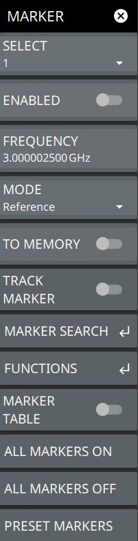
MARKER Menu
SELECT
Selects one of the 8 markers. Marker 1 is selected by default.
ENABLED:
Enables the selected marker. When the toggle is off, the marker is disabled and not shown on the top of the sweep window.
FREQUENCY
Sets the marker frequency. For delta markers, the frequency is relative to the reference marker. Change the marker frequency by dragging it to the desired location. You can also change the marker frequency by pressing the FREQUENCY button and changing it manually using the keypad controls.
MODE
Sets the current active marker as a reference (standard) marker or a delta marker relative to Marker 1. Marker 1 is always a reference marker:
• Normal: A Normal marker is also known as a tracking marker. The frequency is fixed but the amplitude value varies from sweep to sweep. It measures the absolute value of the marker.
• Delta (Δ): A Delta (Δ) marker displays the delta frequency and amplitude between itself and a reference marker. If Marker 1 is selected to be a Delta marker, then Marker 2 is turned on as a reference marker for Marker 1 and it becomes a Normal marker at the same location.
TO MEMORY
If there is a trace in the memory the TO MEMORY toggle will allow the user to save the marker into the memory trace. If the memory trace is not displayed the marker will moved into the memory trace and also not be displayed. Active markers will follow the active trace and the same with memory traces. If there is no trace in memory the toggle will not work. An error message will be displayed in the notifications bar.
TRACK MARKER
Allows the user to track the marker. For example if the user searched peak and changed the graph and used the track marker it will return to the peak.
Sets the position of markers by either moving to left, right or center. There is a capability to set the marker to left most or right most end of the sweep window. For more information about using marker functions, refer to MARKER FUNCTIONS.
MARKER TABLE
Toggle on or off the marker table displayed below the sweep window. Refer to MARKER TABLE for additional information.
ALL MARKERS ON
Turns all markers on, but markers will retain their last frequency position once re-enabled.
ALL MARKERS OFF
Turns all markers off, but markers will retain their last frequency position once re-enabled
PRESET MARKERS:
Presets marker selections to default values.
MARKER SEARCH
Access MARKER SEARCH submenu from MARKER menu.
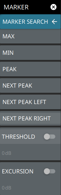
MARKER SEARCH
MARKER SEARCH
Returns to the main MARKER menu.
MAX
Press MAX button to move the active marker to the maximum point on the active trace.
MIN
Press MIN button to move the active marker to the minimum point on the active trace
PEAK
Moves the selected marker to the highest peak.
NEXT PEAK
Moves the selected marker to the next highest peak regardless of location.
NEXT PEAK LEFT
Moves the selected marker to the next peak left of its current position.
NEXT PEAK RIGHT
Moves the selected marker to the next peak right of its current position.
NEXT POINT LEFT
Moves the selected marker one display point to the left of its current position. Useful for fine tuning the position of a marker.
NEXT POINT RIGHT
Moves the selected marker one display point to the right of its current position. Useful for fine tuning the position of a marker.
THRESHOLD
If turned on, sets the threshold that a peak has to achieve to be considered a peak. The default is 0 dB, the min is -200 dB and max is 100 dB.
EXCURSION
If turned on, sets the excursion value that a peak amplitude must rise and fall over the peak threshold to qualify as peak.
MARKER FUNCTIONS
Access FUNCTIONS submenu from MARKER menu
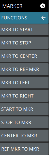
MARKER FUNCTIONS
MKR TO START
Press to set the active marker to the start frequency of the SPAN..
MKR TO STOP
.
MKR TO CENTER
Moves the selected marker to the highest peak.
MKR TO REF MKR
Moves the selected marker to the next highest peak regardless of location.
MKR TO LEFT
Moves the selected marker to the next peak left of its current position.
MKR TO RIGHT
Moves the selected marker to the next peak right of its current position.
START TO MKR
Moves the selected marker one display point to the left of its current position. Useful for fine tuning the position of a marker.
START TO MKR
Moves the selected marker one display point to the right of its current position. Useful for fine tuning the position of a marker.
CENTER TO MKR
If turned on, sets the threshold that a peak has to achieve to be considered a peak.
REF MKR TO MKR
If turned on, sets the excursion value that a peak amplitude must rise and fall over the peak threshold to qualify as peak.
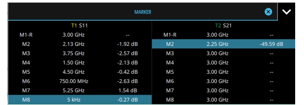
MARKER TABLE
The Marker Table is displayed below the sweep window. The table is automatically sized to display all 8 markers that are turned on. The table displays marker frequency/distance, amplitude, and delta information for delta markers. The selected marker is displayed with a highlighted background. Table controls are located on the right of the header. Select the down or up arrow to collapse or expand the table, press X to close the table.
Marker Table
You can select and change the marker parameters by selecting the marker from either the MARKER menu or the MARKER table.
The currently selected marker’s value is shown at the top left of the sweep window with its current amplitude and frequency values. The selected marker is highlighted on the trace display.