Access CALIBRATE menu from main menu to mainly perform calibration, access cal setup and choose a calibration method and so on.
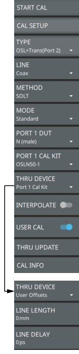
CALIBRATE Menu
START CAL
Begins VNA calibration.
CAL SETUP
Opens CAL SETUP dialog. Provides the predefined set of parameters needed to start calibration.
TYPE
Selects any one of the following calibration types, see TYPE:
• OSL
• OSL +Trans (USB Sen)
• OSL + Trans (2-port)
• Trans (USB Sen)
• Trans (2-port)
• iOSL (not available when LINE is set to Waveguide)
• iOSL + Trans (USB Sen) (not available when LINE is set to Waveguide)
• iOSL + Trans (2-port) (not available when LINE is set to Waveguide)
• Reflection Response
LINE
Sets the cable type to either Coax or Waveguide.
METHOD
Selects any one of the following calibration methods:
• SOLT: Short-Open-Load-Thru calibration method is default when LINE is set to Coax. The load behavior largely sets the directivity terms, the short and open together largely determine source match and reflection tracking and the thru largely determines transmission tracking and load match. See SOLT Calibration.
• SSLT: Short-Short-Load-Thru calibration method is default when LINE is set to Waveguide. It differs from an SOLT calibration by the differing offset lengths between two shorts which are used to help define reflection behavior instead of an open and short. See SSLT Calibration.
MODE
Selects the calibration mode as either Standard or Flex.
PORT 1 DUT
Selects an appropriate PORT 1 DUT connector. Not available when TYPE is set to any one of the ICN51A InstaCal calibration types.
PORT 1 CAL KIT
Selects an appropriate PORT 1 CAL KIT connector. Not available if THRU DEVICE is set to User Offsets and when TYPE is set to any one of the ICN51A InstaCal calibration types.
THRU DEVICE
Selects the thru device as either PORT 1 CAL KIT or User Offsets. Enter the LINE LENGTH and LINE DELAY, when THRU DEVICE is set to User Offsets.
INTERPOLATE
Turns on/off data interpolation. If the toggle is turned off, the calibration data will not be interpolated from one point to another. This means the user cannot change the frequency. When it is turned on, the unit will take the data and allow the user to change the frequency because it will interpolate the data between two points.
USER CAL
Enables user calibration when toggled on.
THRU UPDATE
Opens the calibration wizard to allow calibrating the Thru component without repeating the entire calibration sequence.
CAL INFO
Displays the active cal settings and current instrument settings. See CAL INFO.
CAL SETUP
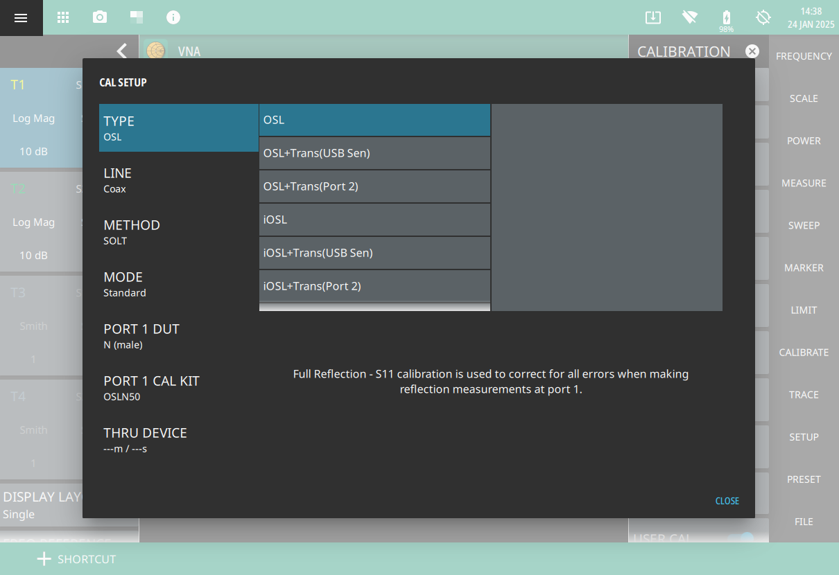
In order to perform a proper calibration, several parameters must be set before the calibration procedure is started. These parameters are: TYPE, LINE, METHOD, MODE, PORT 1 DUT, PORT 1 CAL KIT and THRU DEVICE as shown in Figure: CAL SETUP Window. To access Cal Setup window, press the CAL SETUP submenu from CALIBRATE menu.
CAL SETUP Window
TYPE
MS2085A/89A Site Master supports the following calibration types in VNA mode as shown in Figure: CAL SETUP Window.
Refer to Cable Antenna Analyzer (CAA) Measurement Guide (PN: 10580-00493) for detailed information on each calibration type except Reflection Response. Some of the calibration types are option dependent, please refer to your instrument’s technical data sheet for the list of available options.
OSL (Open-Short-Load)
For all measurement except Transmission (USB Sensor), you can manually calibrate the unit using an external precision OSL calibration kit.
OSL +Trans (USB Sen)
The combined calibration type OSL + Trans (USB Sen) allows the instrument to be calibrated once for all the supported measurement types, eliminating the need to re-calibrate when switching from one type of measurement to another, such as return loss to transmission.
OSL + Trans (2-port) (Option 21)
OSL + Transmission (2-Port) type involves calibrating the port one with OSL and then calibrating the transmission from port 1 to port 2. The cable used to connect the two ports would be normalized.
Transmission (2-Port) (Option 21)
The 2-port transmission measurement is used to verify the performance of tower-mounted amplifiers, and duplexers, and to verify antenna isolation between two sectors. The excellent dynamic range makes it suitable for repeaters as well. The second port is a selective receiver which provides up to 100 dB dynamic range which makes it possible to test the band pass filters common on many networks.
iOSL
The system will automatically switch between open, short and load during the calibration process. Note that this calibration type is only available when InstaCal ICN51A is connected and LINE is set to Coax.
iOSL + Trans (USB Sen)
The system will automatically switch between and open, short and load. ICN51A InstaCal is used in this type instead of traditional OSL. External USB power sensor is necessary to carry out this calibration type. Note that this calibration type is only available when InstaCal ICN51A is connected and LINE is set to Coax.
iOSL + Trans (2-port) (Option 21)
Just like OSL+ Trans (USB Sen) the iOSL + Trans (2-Port) uses the ICN51A instead of a traditional OSL. The system will automatically switch between and open, short and load. Note that this calibration type is only available when InstaCal ICN51A is connected and LINE is set to Coax.
Reflection Response
This calibration type simply performs normalization for Port 1. This cal type requires one connection to Port 1 reflection measurements only. Connect Open or Short on Port 1, load connection can be skipped, but if used, will improve the effectiveness of this calibration.
Follow the steps below to perform Reflection Response calibration:
1. Select FREQUENCY on the main menu and adjust the start and stop frequency values if needed.
If the active calibration mode is Standard and USER CAL is on, a warning message is displayed informing you that USER CAL must be turned off. You can use the Flex calibration mode to allow frequency changes with USER CAL on.
2. Select CALIBRATE on the main menu and ensure USER CAL is off.
3. Go to TYPE drop-down and select Reflection Response.
4. Select MODE and select either Standard or Flex.
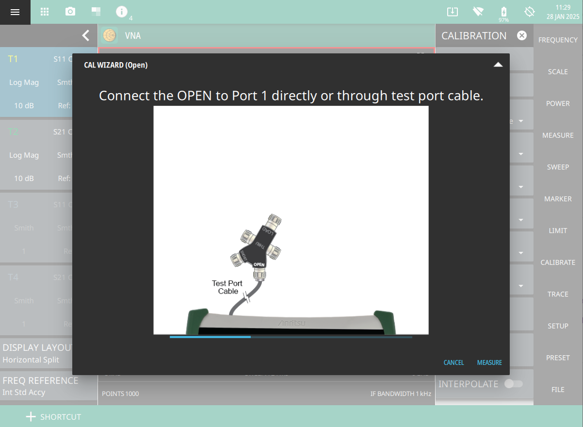
5. Select START CAL and follow the on-screen CAL WIZARD.
6. Select MEASURE at the end of each step to proceed to the next step in the sequence.
Reflection Response Calibration - Open
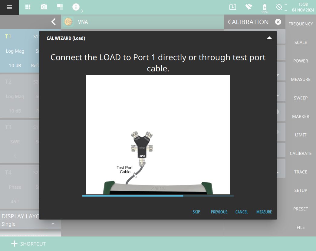
7. Select SKIP as connecting the Port 1 to LOAD is optional, but if used, will improve the effectiveness of this calibration.
Reflection Response Calibration - Load
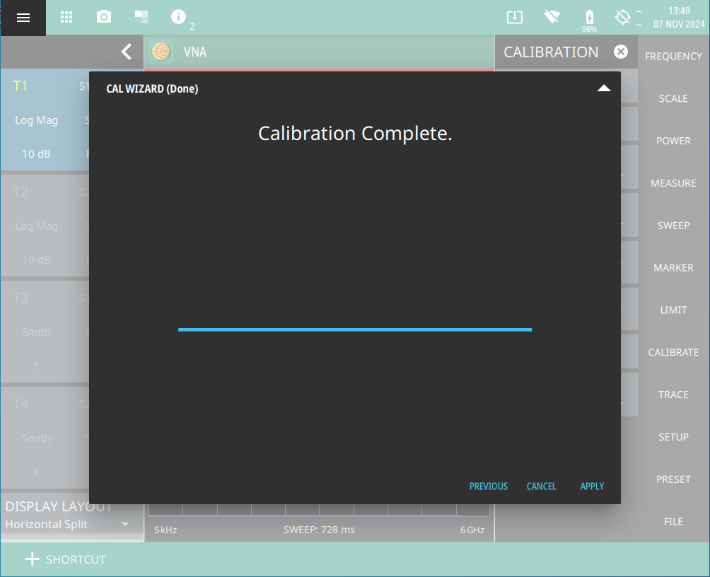
8. When done, touch APPLY.
Reflection Response Calibration - Done
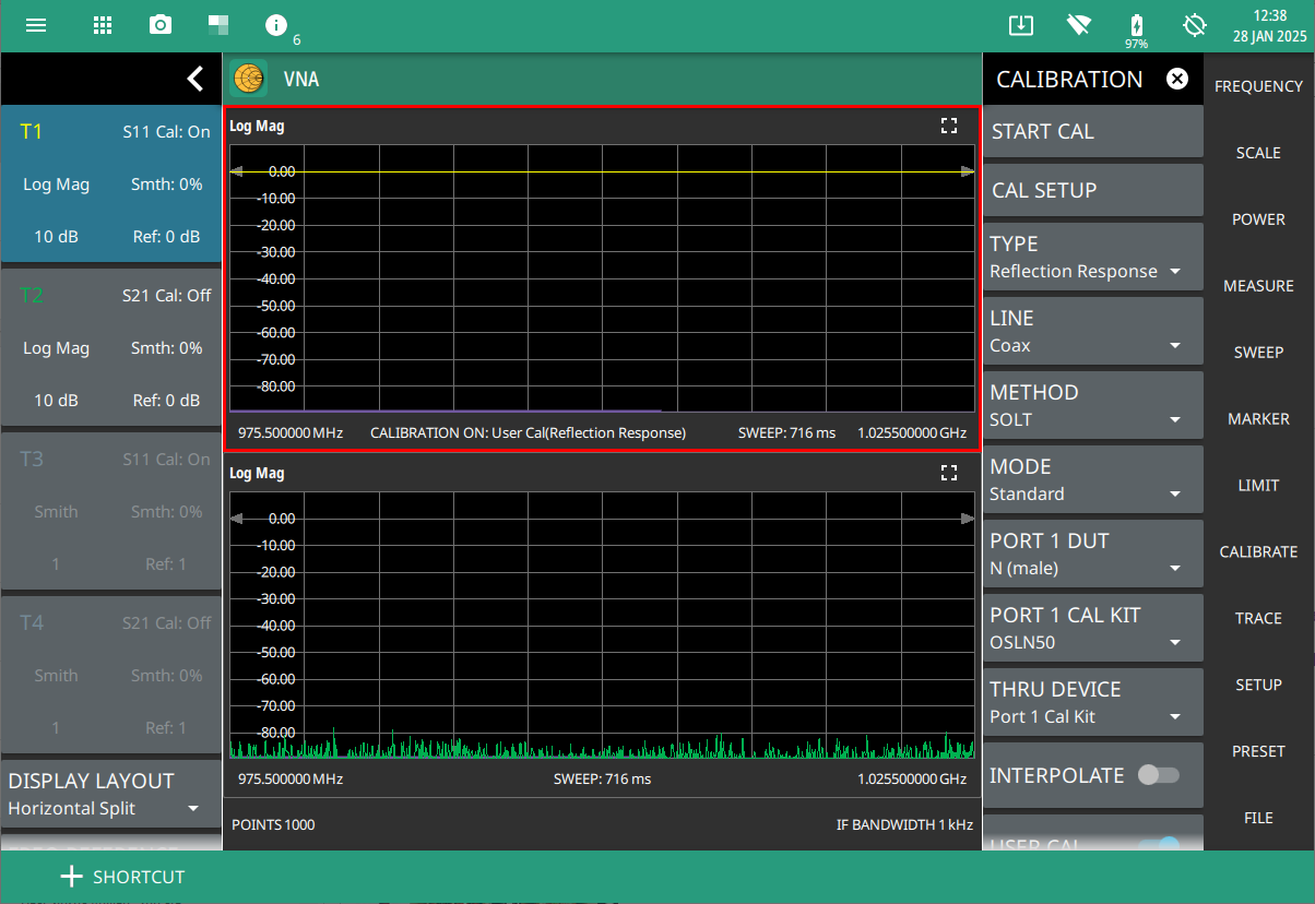
9. When calibration has completed, the user cal status message will display as follows:
CALIBRATION ON: User Cal (Reflection Response) for Standard calibration mode CALIBRATION ON: iUser Cal (Reflection Response) for Flex calibration mode
Notice that when the Site Master is connected with ICN51A InstaCal and if TYPE is set to any one of the
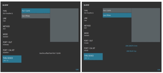
calibration types such as iOSL, iOSL + Trans (USB Sen) and iOSL + Trans (Port 2), the PORT 1 DUT and PORT 1 CAL KIT parameters disappear from Cal Setup window as shown in Figure: CAL SETUP Window - TYPE. Also notice that InstaCal calibration types are not available when LINE is set to Waveguide, as shown in Figure: CAL SETUP Window - TYPE.
CAL SETUP Window - TYPE
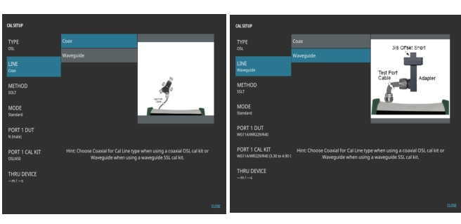
LINE
The Site Master supports measurements and calibrations for both coaxial and waveguide media. In the Cal Setup window, set the LINE to either Coax or Waveguide before starting the calibration. Figure: Cal Setup Window - Coaxial Line (left) and Waveguide Line (right) shows the selection window for the Line, within the CAL SETUP window.
Cal Setup Window - Coaxial Line (left) and Waveguide Line (right)
CALIBRATION METHODS
In Vector Network Analyzer, calibration is required when the test port cable or adapters have been changed or when no valid calibration is available (Cal: Off). The following sections describe how to perform calibrations.
Note
If a Test Port Extension Cable is to be used (this is recommended), then it must be connected to the Site Master before calibration.
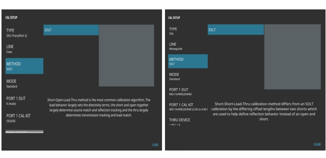
For coaxial line types, the calibration method that is most commonly used is the Short, Open, Load, Thru method, or SOLT. For waveguide line types, the calibration method that is most commonly used is the Offset Short 1 (1/8th wavelength), Offset Short 2 (3/8th wavelength), Load, Thru method, or SSLT. Use METHOD to set the appropriate method for the type line being used during the calibration and measurements, as shown in Figure: Cal Setup Window - SOLT Method (left) and SSLT Method (right)
Cal Setup Window - SOLT Method (left) and SSLT Method (right)
You can manually calibrate the instrument or use the ReadyCal factory calibration for quick measurements. The instrument automatically applies the default ReadyCal to all vector network analyzer measurement types. The instrument needs to be manually re-calibrated if a test port cable is used and has been replaced, or when changing frequency in Standard Cal Type (not in Flex Cal).
To manually calibrate the instrument:
1. Select FREQUENCY from the main menu and enter the appropriate frequency range.
2. Select POWER menu from main menu to set PORT 1 POWER level.
3. Select CALIBRATE on the main menu and press CAL SETUP to make changes to the setup as needed. Refer to CAL SETUP.
4. Press START CAL from CALIBRATE menu. Note that INTERPOLATE and USER CAL toggles cannot be turned on before calibrating the instrument.
5. Confirm the calibration status of the appropriate S-Parameter by verifying the cal status displayed as ON in the status panel. This indicates that calibration has been applied to the appropriate S-Parameter. By default the trace card in the status panel shows the cal status as off, indicating either the calibration is not applied or inappropriate S-parameter has been selected.
SOLT Calibration
Follow the steps below to perform SOLT calibration method:
1. Select FREQUENCY on the main menu and enter the appropriate frequency range.
A warning message will be displayed informing you to turn off USER CAL in order to change the active calibration type.
2. Select CALIBRATE on the main menu and ensure USER CAL is off.
3. Select TYPE and choose a desired cal type for example, OSL + Trans (Port 2).
4. Select LINE and select Coax. The cal method for coaxial media is SOLT by default.
5. Select MODE and select either Standard or Flex.
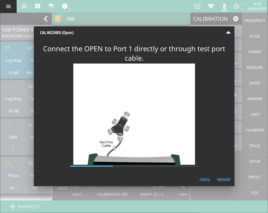
6. Select START CAL and follow the on-screen CAL WIZARD.
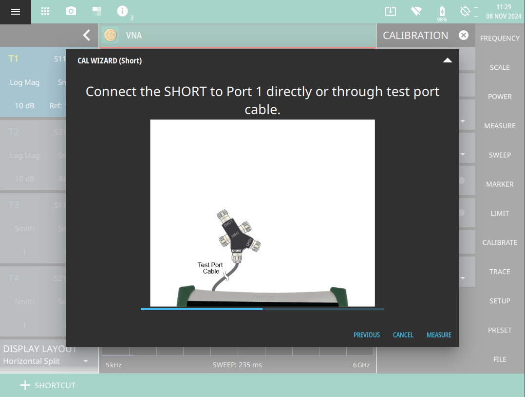
7. Select MEASURE at the end of each step to proceed to the next step in the sequence.
SOLT Calibration Method- OPEN
SOLT Calibration Method- SHORT
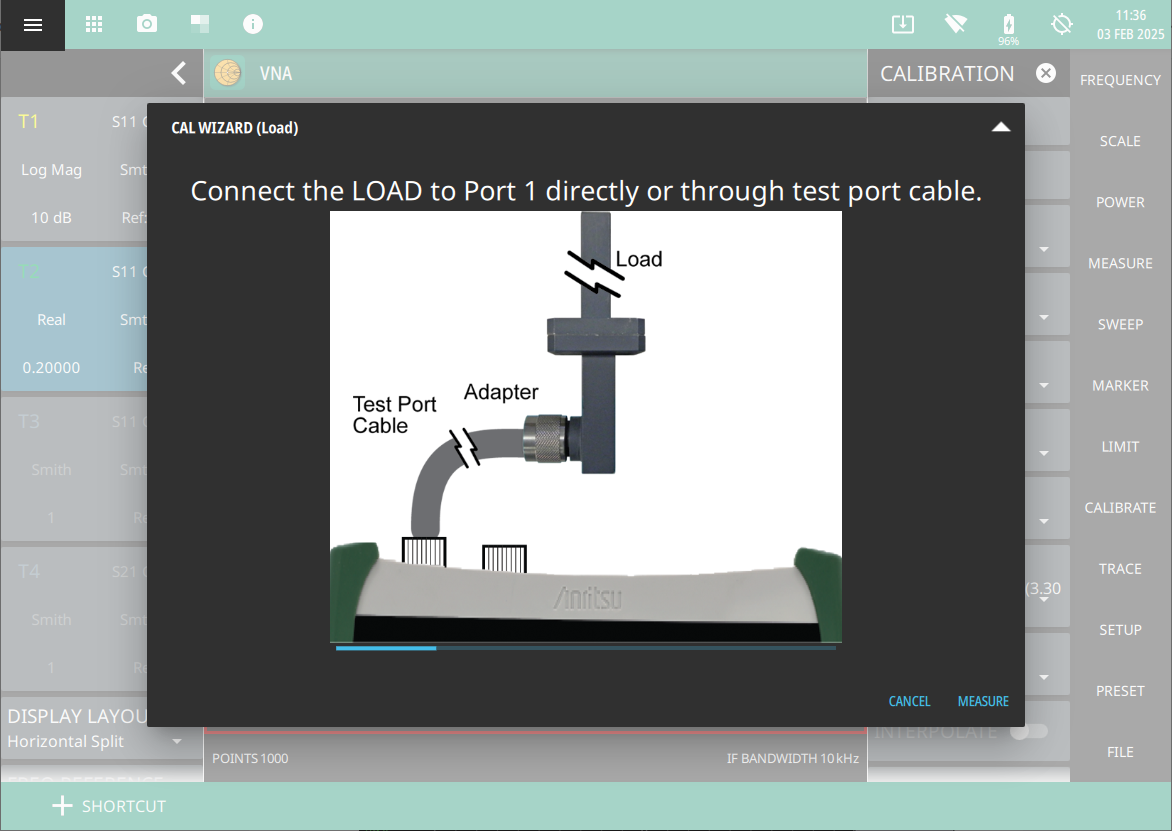
SOLT Calibration Method - LOAD
8. When done, touch APPLY.
SOLT Calibration Method - Done
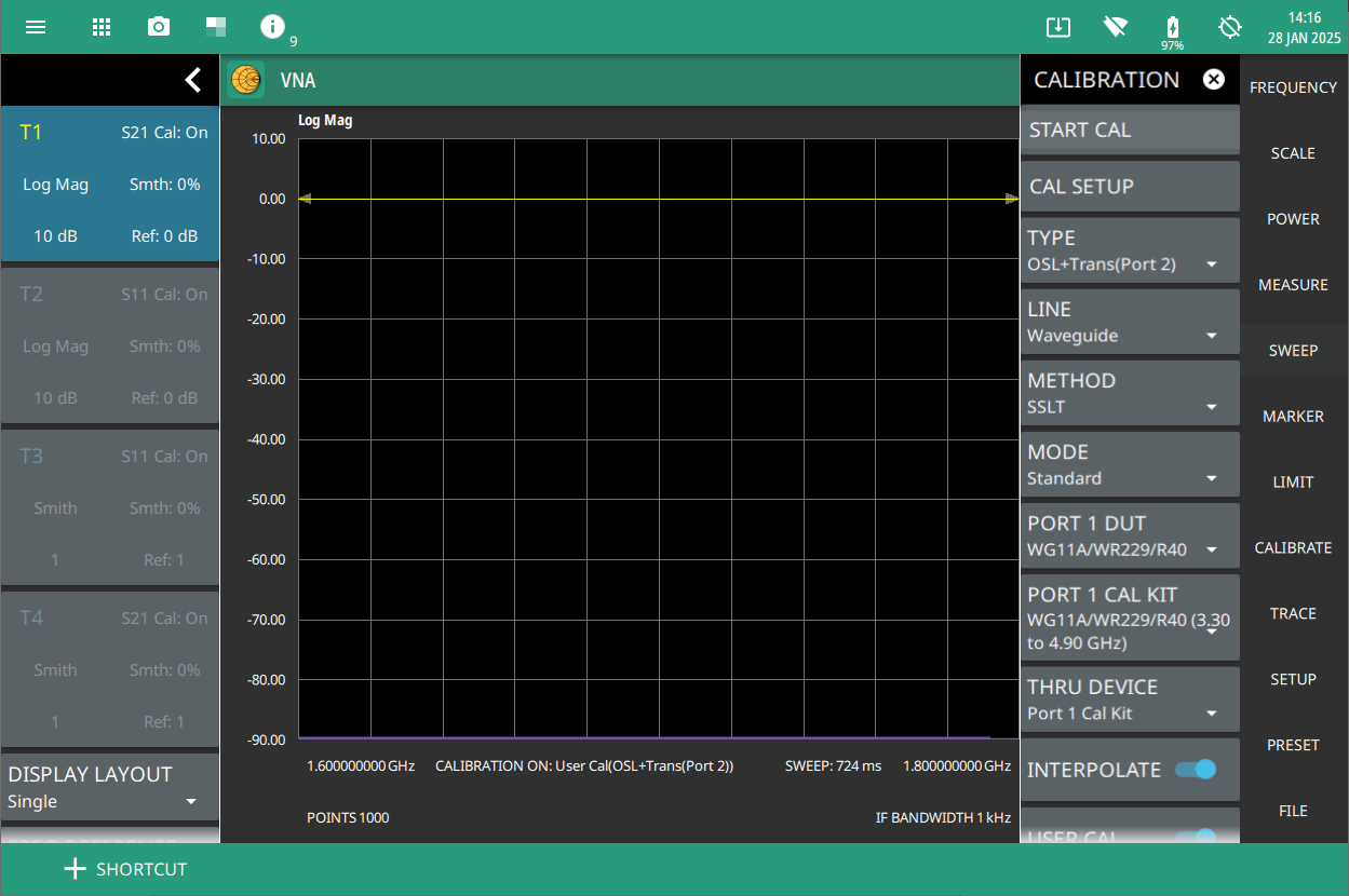
9. When calibration has completed, the user cal status message will display as follows:
CALIBRATION ON: User Cal (OSL + Trans (Port 2)) for Standard calibration type CALIBRATION ON: iUser Cal (OSL + + Trans (Port 2)) for Flex calibration type
Follow the steps below to perform SSLT calibration method:
1. Select FREQUENCY on the main menu and adjust the start and stop frequency values if needed.
A warning message will be displayed informing you to turn off USER CAL in order to change the active calibration type.
2. Select CALIBRATE on the main menu and ensure USER CAL is off.
3. Select TYPE and choose a desired cal type for example, OSL + Trans (Port 2).
4. Press LINE and choose Waveguide. The cal method for waveguide media is SSLT by default.
5. Select MODE and select either Standard or Flex.
6. Select START CAL and follow the on-screen CAL WIZARD.
7. Select MEASURE at the end of each step to proceed to the next step in the sequence.
SSLT Calibration Method - Load
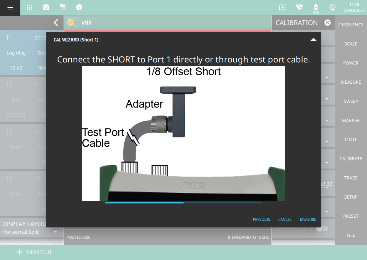
SSLT Calibration Method - Short 1
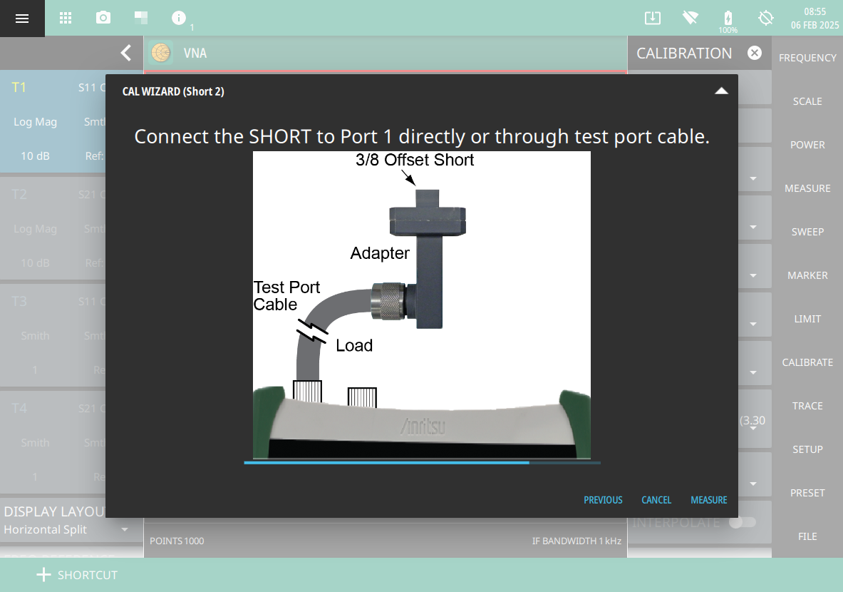
SSLT Calibration Method - Short 2
8. When done, touch APPLY.
SSLT Calibration Method - Done
9. When calibration has completed, the user cal status message will display as follows:
CALIBRATION ON: User Cal (OSL + Trans (Port 2)) for Standard calibration type CALIBRATION ON: iUser Cal (OSL + Trans (Port 2)) for Flex calibration type
The available calibration modes are Standard Cal and Flex Cal. Standard Cal applies to the currently set frequency range. Changing either the Start or Stop Frequency setting requires turning off User Cal, in which case the factory default 1-Port ReadyCal will apply to all measurement types except Transmission (USB Sensor). You may subsequently re-calibrate the instrument as appropriate.
Flex Cal calibrates the instrument over the entire frequency range and interpolates data points if the frequency range is changed. This method saves time as it does not require the user to re-calibrate the system for frequency changes. The trade-off is fewer data points and less accuracy when compared to Standard Cal.
Table: Summary of Calibration Types lists the main characteristics of the Standard and Flex calibration types. If you do not expect to change the frequency range often, Standard Cal is recommended for best accuracy.
Summary of Calibration Types
Calibration Mode
Characteristics
Standard Cal
Need to re-calibrate if frequency changes.
This will provide the best accuracy.
Recommended for reporting.
Flex Cal
No need to recalibrate if frequency changes.
Recommended for troubleshooting.
PORT 1 DUT AND PORT 1 CAL KIT
For the most accurate calibrations, you must select the connector of the DUT that will be attached to Port 1 of the instrument. After you select the DUT connector, you must then select the desired calibration kit that will be used for the Port 1 correction. If you do not select a desired calibration kit, then the analyzer defaults to one of the built-in kits.
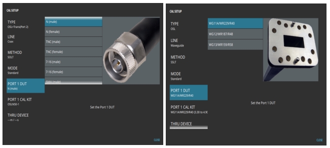
Cal Setup Window - Coaxial Port 1 DUT (left) and Waveguide Port 1 DUT (right)
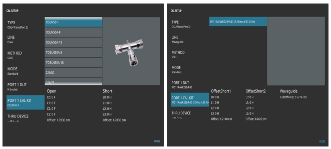
Cal Setup Window - Coaxial Port 1 CAL KIT (left) and Waveguide Port 1 CAL KIT (right)
The selection list for DUT connectors includes all of the common connectors that you may encounter. Table: Coax DUT Connectors and Cal Kits and Table: Waveguide DUT Connectors provide complete list of Coax and Waveguide connectors and corresponding calibration kits that are selectable through the Cal Setup window.
After you have set up Port 1 DUT and PORT 1 Cal Kits, you must also set the Thru device that is used in the Thru step of the calibration that is being conducted, if applicable. The Thru device accounts for any extra length that is used during the calibration steps (such as an adapter) but is removed for the actual measurement of the DUT. In these cases, if the Thru device length is not accounted for, then the resulting measurements will have an offset error. The Thru device length can be set in units of distance or time, or it can be set to equal the Thru length offset of the cal kits that are used for Port 1, if applicable. Figure: Cal Setup Window - Thru Device shows the selection window for the Thru device setting. Press LINE LENGTH to enter the length of the Thru device using the numeric keypad, you can also select appropriate units. Alternatively, you can press LINE DELAY to enter the device length in unit of time.
Cal Setup Window - Thru Device
INTERPOLATE
If INTERPOLATE toggle is turned off and the current Cal status is on and valid, you cannot modify the frequency range or the source power level, or increase the number of points above 16,001 points (assuming the calibration was performed with 16,001 points or less). Any of these changes will require the USER CAL to be turned off and a new calibration to be performed. You can, however, adjust the number of points from 2 to 16,001 without forcing the calibration to become invalid. To use 2065 points, the number of points must be set to 2065 before the calibration is started. If your current Cal status is on and you turn INTERPOLATE on, you can then change the frequency range (smaller and anywhere within the calibrated range) or modify the number of points without invalidating the calibration. In that case, the calibration coefficients are regenerated (interpolated) to match the new settings. You cannot increase the frequency range, however, beyond the range that was used during calibration. For example, you could perform a calibration from 1 MHz to 6 GHz using 2065 points. With Interpolate toggle on, you could then make a measurement by zooming in on a desired frequency range, 410 MHz to 435 MHz, for example. The trace in your measurement would use the full 2065 points within this much narrower frequency range.
USER CAL
USER CAL toggle in CALIBRATE menu is turned on automatically after the calibration process has been completed successfully. When USER CAL is on, the calibration coefficients are applied to the measured data, resulting in corrected S‑parameter data. You can turn USER CAL Off, which results in trace data using uncorrected (or raw) S‑parameter data and losing the calibration status.
THRU UPDATE
When measuring the transmission (or insertion loss) response of a DUT, the calibration requires a Thru measurement to be performed. This requires at least one external cable to be introduced into the calibration. The additional cable component is the most susceptible to changes from environmental conditions, such as temperature changes and mechanical flexing. The Thru Update allows you to quickly eliminate the effects of temperature changes or of changes caused by mechanical flexing of the cable without having to repeat the entire calibration process. The Thru update is particularly useful when viewing DUT transmission responses with small scale resolution (0.5 dB/division or less).
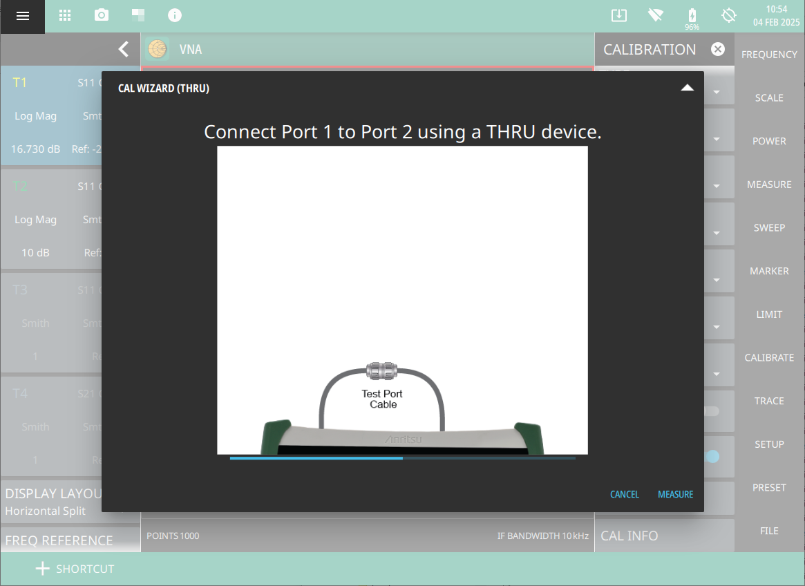
Figure: Thru Update - Thru shows the calibration wizard window depicting the calibration setup and calibration steps.
Thru Update - Thru
Thru Update - Done
CAL INFO
In order to perform a proper calibration, several parameters must be set before the calibration procedure is started. These parameters are: TYPE, METHOD, MODE, LINE, PORT 1 DUT, PORT 1 CAL KIT and THRU device.
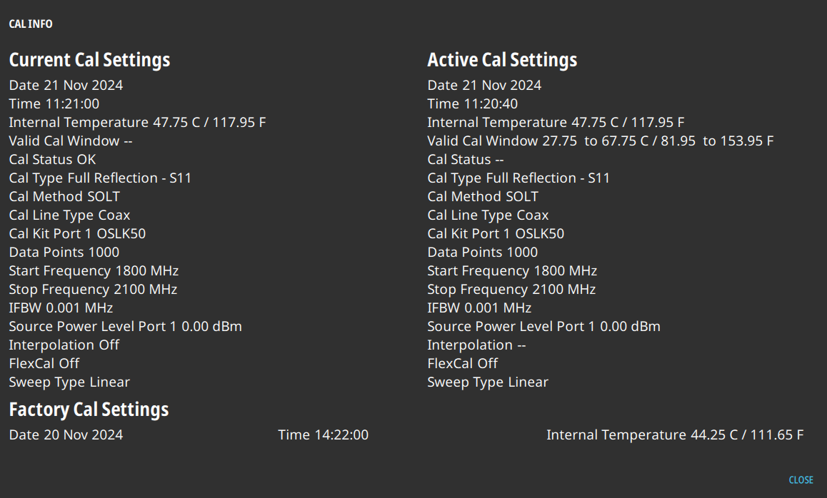
To view a summary of these settings, begin from the CALIBRATE main menu and press CAL INFO submenu. A summary of the Active Cal Settings and the Current Settings of the instrument are displayed (see Figure: CAL INFO Window). Press CLOSE to close the CAL INFO window.
CAL INFO Window
The CAL INFO window displays all of the key setup parameters for the calibration. The current settings are shown on the left, and the settings of the instrument at the time of the last calibration are shown on the right.