![]() |
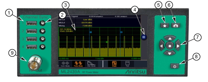
1. USB Power Sensor Input Ports: Four standard USB 2.0 Type A sensor inputs are located on the front and rear panels. Use these ports to insert USB power sensors or external memory device. 2. Trigger Input Ports (Only for MA244xxA sensors): Four standard SMB sensor trigger inputs are located on the front and rear panels. 3. Display Screen: 5-inch WVGA multi-touch display screen. 4. 3-Line Icon: Shows the Main menu when pressed. Refer to Main Menu for more information. 5. Favorites Key: Favorites key enables the user to setup a customized menu to provide grouping frequently used menu items into one convenient menu. 6. Camera: Saves the screenshot of the display screen. The internally stored images can be copied to an external USB storage device. Refer to the Copying Screenshots to External Memory Device on how to retrieve the stored screenshots. 7. Keypad: Use the ◄ ► to move right or left on the display and in the menus. Use ▲ ▼ for incrementing or decrementing numeric parameters, or scrolling through multi-line or multi-page displays. Use the center keypad to select an on-screen item or menu and complete a numeric or pick-list entry. 8. On/Standby Button: Toggles the instrument between “on” and “standby”. Entering standby mode will perform a save of the internal circuits modes and will perform a save of the current instrument state before shutdown. Pressing and holding the On/Standby key for several seconds will force standby mode if the instrument has become non-responsive. In this case, no context save is performed. 9. RF Out: The output of the built-in 50 MHz programmable test source is available from a Type-N connector located on the front, or optionally on the rear panel of the instrument. This test source is used to verify basic performance of sensors used with the ML2439A. |
![]() |
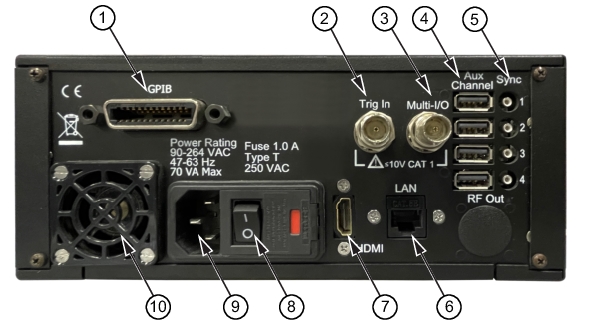
1. GPIB: 24-pin GPIB (IEEE-488) connector for connecting the power meter to the remote control General Purpose Instrument Bus. GPIB parameters can be configured through the menu. 2. BNC Trigger Input: BNC input for connecting an external trigger signal to the power meter. Voltage range is ±5 volts, but the input impedance is 1 Megohm to allow use of common 10x oscilloscope probe for a ±50 volt input range. 3. BNC Multi I/O: Input/Output port. 4. USB Sensor Inputs: Four sensor inputs are located on the front and rear panels of the instrument. These are standard USB 2.0 Type A receptacles designed to accept only Anritsu power sensors or standard USB keyboards, mice, and flash drives. 5. Trigger Inputs: Four sensor trigger inputs are located on the front and rear panels of the instrument. These are standard SMB receptacles designed to accept only Anritsu power sensor trigger cables. 6. LAN: Connector for remote control and firmware updates. Allows DHCP or fixed (IP / Subnet) setting mode. LAN parameters can be configured through the menu. 7. HDMI: Receptacle for connecting an external monitor to mirror front panel display. The image resolution will be 800 x 480 and will be stretched to fit the external full display size. 8. On/Off Switch: The power switch is used to shut off main instrument power. 9. AC Mains Input: The module accepts a standard AC line cord, included with the power meter. The safety fuse may also be accessed once the line cord is removed. The instrument’s power supply accepts 90 to 264 VAC, so no line voltage selection switch is necessary. 10. Cooling Fan: The cooling fan ventilates the internal heat from the instrument. Keep the fan inlet and exhaust ports clear of obstructions at all times for proper ventilation and cooling of the instrument. |
![]() |
Note | The base ML2439A model operates two sensors at a time. With the ML2439A-004 Option, four sensors can be active at any given time. |
![]() |