This chapter provides a description of functions that provide additional calibration, post-processing, and display options that increase the usefulness of the instrument data. The topics described include: embedding/de-embedding, reference-plane control and modification, and impedance transformations.
A number of functions are provided beyond the basic calibration and display tools to help post-process the data in a way that is useful. The topics described relate to virtually modifying the environment in which the DUT resides.
These topics include
• Embedding/De-embedding
This is the virtual removal or insertion of networks or circuits around a DUT that may represent fixtures, launching structures, tuning elements, or other items.
• Reference Plane Control
This can be thought of as a simpler subset of de-embedding in which transmission line lengths and loss are removed from the measured data.
• Impedance Transformation
When calibration components are not available in impedances other than 50 ohms, it is possible to view the data as if the VNA had been calibrated in some other impedance.
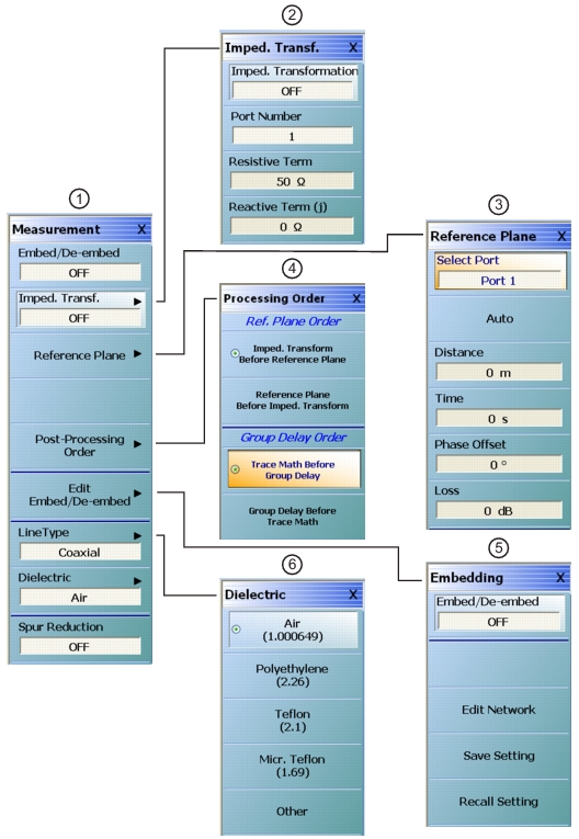
In addition, there are some clerical tasks to describe including the order of virtual operations and some conversions to other parameter formats (impedances and admittances for example). The measurements menu that contains the majority of these functions is shown below (Figure: REFERENCE PLANE Control Menu). Parameter conversions are a per-trace function (as opposed to the others which are per channel) and is listed under the DISPLAY menu.
The MEASUREMENT Menu Set
Use menus #1, #3, #4, and #5 for Embedding/De-embedding.