2K, 4K, 8K Modes (DVB‑T/H) and Modes 1, 2, and 3 (ISDB‑T)
DVB‑T/H and ISDB‑T are multi-carrier systems that use thousands of data carriers, each of which carries QPSK (Quadrature Phase Shift Keying), 16QAM, or 64QAM data. Pilot carriers use BPSK (Binary Phase Shift Keying) or DBPSK (Differential BPSK). QAM (Quadrature Amplitude Modulation) is one available method that is used to increase the amount of information per modulation symbol.
In BPSK, 1 bit can be coded per symbol. In QPSK, 2 bits can be coded per symbol. In 16QAM, 4 bits can be coded per symbol, In 64QAM, 6 bits can be coded per symbol.
Using a smaller number of subcarriers (2K mode in DVB‑T/H, or Mode 1 in ISDB‑T) allows for more inter-carrier spacing and thereby provides more tolerance to echoes that are influenced by Doppler effect. Shorter symbol duration limits the maximum delay of accepted echoes. Using a larger number of subcarriers creates smaller inter-carrier spacing and provides a longer symbol duration. The choice among these modes is based upon balancing the influence of Doppler effect against the maximum delay of echoes. The number of subcarriers has no impact on the broadcast capacity. For receivers that are in motion, signal complexity evolves from the many echoes that are received (which are delayed in the time domain) and also from the frequency shift (the Doppler effect) that distorts both the incoming signal and the echoes.
DVB‑T/H
DVB‑T/H uses OFDM (Orthogonal Frequency Division Multiplex) transmission. All of the data carriers that are in one OFDM frame are modulated by using QPSK, 16QAM, or 64QAM. In addition, the 16QAM and 64QAM modulation can use hierarchical transmission, which changes the proportions of the constellations.
The transmitted signal is organized in OFDM frames. Each frame has a duration of TF and consists of 68 OFDM symbols, which are numbered from 0 to 67. Each symbol contains a set of K carriers (where K = 6817 carriers in the 8K mode, and K = 1705 carriers in the 2K mode). Symbols are transmitted with a duration of TS. In addition, each symbol is composed of 2 parts, a useful part with duration of TU and a guard interval with duration of Delta (Δ).
OFDM signals are composed of multiple separately‑modulated carriers. Each symbol can be considered to be divided into cells, which each correspond to the modulation that is carried on one carrier during one symbol. All symbols contain data and reference information. The reference information includes scattered pilot cells, continual pilot carriers, and TPS carriers.
The pilots can be used for frame, frequency, and time synchronization and also for transmission mode identification and channel estimation, as well as being used to follow the phase noise.
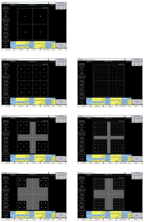
The proportions of the constellations depend on a hierarchical modulation parameter called alpha (α). Alpha can have 3 values: 1, 2, or 4. α is the minimum distance between any 2 constellation points that carry different High‑Priority‑bit (HP‑bit) values divided by the minimum distance separating any 2 constellation points. Figure: DVB‑T/H Modulation and Hierarchy Settings shows examples of constellations and hierarchy settings. Images on your instrument may differ from those in this figure.
In DVB‑T/H, the hierarchical system maps the data onto 16QAM or 64QAM in such a way that a QPSK stream is effectively buried within the 16QAM or 64QAM stream. In addition, the spacing between constellation states can be adjusted (by use of hierarchy settings) to protect the QPSK (HP) stream at the expense of the 16QAM or 64QAM (LP) stream. HP and LP stand for High Priority and Low Priority. This is described further in section Hierarchical Modulation.
In a 64QAM constellation using hierarchical modulation, the two most significant bits (MSB) would be used for robust mobile service. The remaining 4 bits could contain an HDTV service (for example). The first two MSB (most significant bits) correspond to a QPSK service that is embedded in the 64QAM service.
Good quality reception allows receivers to resolve the entire 64QAM constellation. In areas with reception of poorer quality, or in the case of mobile or portable reception, receivers may be able to resolve only those portions of the constellation that correspond to QPSK (the High Priority stream).
• Hierarchy None or Hierarchy 1 for 16QAM and 64QAM
• Hierarchy 2 for 16QAM and 64QAM
• Hierarchy 4 for 16QAM and 64QAM
DVB‑T/H Modulation and Hierarchy Settings
Guard Intervals
In order to decrease symbol interference and to reduce sensitivity to time synchronization problems, each OFDM (Orthogonal Frequency Division Multiplexing) symbol is extended by a guard interval (GI), placing a copy of the end of the OFDM symbol at the front of the symbol, thereby creating a cyclic prefix. The width of a guard interval can be 1/4, 1/8, 1/16, or 1/32 the length of the original symbol. This fraction represents the ratio between the guard interval and the active symbol period. The overall data capacity is reduced by the same fractional proportion. The fraction size of the Guard Interval is selected by using the Mode, GI submenu key. Refer to the Mode, GI submenu key in the following locations:
Guard Intervals are used to ensure that distinct transmissions do not interfere with one another. Guard Intervals introduce immunity to propagation delays, echoes, and reflection, to which digital data is normally very sensitive. A GI at the beginning of each symbol allows time for echoes to fade before the active symbol period begins. Protection is inversely proportional to data rate efficiency. A 1/32 GI (smallest size) gives high data rate efficiency and the lowest protection, while a 1/4 GI (largest size) provides the best protection but the lowest data rate efficiency. Guard Intervals help to reduce echo interference at the receiver if the duration of the echoes does not exceed the duration of the guard interval.
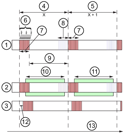
Figure: FFT Start and Guard Interval illustrates a Guard Interval that is one‑fourth of the effective symbol. Note that it could also have been one‑eighth, one‑sixteenth, or one‑thirty‑second of the length of the Effective Symbol.
FFT Start
The FFT Start position is used to synchronize the reading of the OFDM frame. The start can be set at the end of the complete Guard Interval (GI), at the beginning of the GI, or can be set to include only a fraction of the GI, which is divided into eight parts. In other words, the FFT Start may be set in eighths, from 0⁄8 (none of the GI) to 8⁄8 (all of the GI). This control is used in the modulation analysis measurements and the transmitter carrier MER measurements. The flexibility that is provided by a selection of FFT Start positions allows synchronizing with a strong signal. Refer to Figure: FFT Start and Guard Interval.
FFT Start and Guard Interval
1
Direct Wave with Guard Interval shown
2
Direct Wave with FFT Window shown
3
Delayed Wave with Guard Interval shown
4
Symbol X, Length with 1/4 Guard Interval (GI is 1/4 the length of the Effective Symbol)
5
Symbol X + 1, Length with 1/4 Guard Interval
6
FFT Start Positions (a fraction of the Guard Interval) — Refer to FFT Start