Digital Video Broadcast – Terrestrial and Handheld (DVB‑T/H)
DVB‑T
DVB‑T (terrestrial DVB) is a multi-carrier system that uses approximately 2000 data carriers or 8000 data carriers, each of which carries QPSK (Quadrature Phase Shift Keying), 16QAM, or 64QAM data. Pilot carriers use BPSK (Binary Phase Shift Keying) or DBPSK (Differential BPSK). For more information about Phase Shift Keying, refer to Digital Television Signal Analyzer Technology.
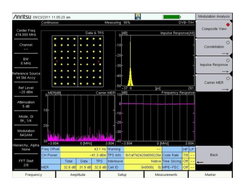
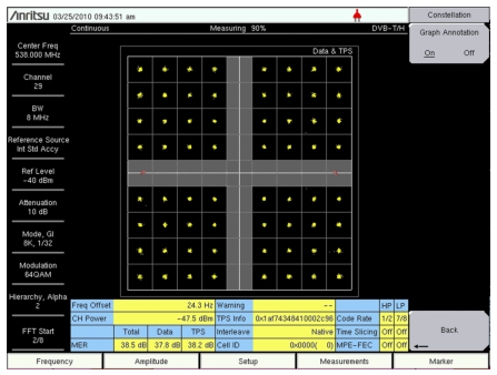
Figure: A 64QAM Constellation Graph in Composite View shows a 64QAM constellation graph. The Instrument Settings Summary displays the Center Frequency, Channel, Bandwidth, Mode, GI setting, Modulation setting (64QAM), and FFT Start position.
A 64QAM Constellation Graph in Composite View
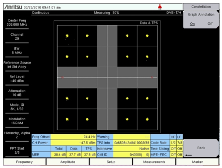
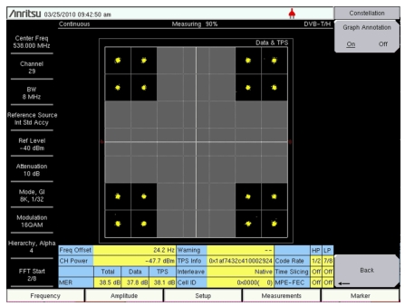
When the signal is transmitted in hierarchy mode, good quality reception allows receivers to resolve the entire 64QAM constellation. In areas with reception of poorer quality, or in the case of mobile or portable reception, receivers may be able to resolve only those portions of the constellation that correspond to QPSK (the High Priority stream).
DVB‑H
DVB‑H (handheld or mobile DVB) uses the DVB‑T transmission system as the physical layer and adds extra error correction and time‑slicing mechanisms on the link layer. DVB‑H carries IP datagrams that are encapsulated by using multi‑protocol encapsulation. DVB‑H differs from DVB‑T by using approximately 4000 data carriers (with QPSK, 16QAM, or 64QAM) as well as 2000 data carriers or 8000 data carriers.
A full DVB‑H system is defined by combining elements in the physical and link layers as well as service information. DVB‑H makes use of the following technology elements for the link layer and the physical layer:
Link Layer
• Time-slicing to reduce average power consumption of terminal and to enable smooth and seamless frequency handover
• Forward error correction for multi-protocol encapsulated data (MPE‑FEC) for improvement in the C/N (carrier‑to‑noise ratio) and Doppler performance in mobile channels, also improving tolerance to impulse interference
MPE‑FEC: Forward Error Correction (FEC) at the Multi‑Protocol Encapsulation (MPE) layer
Physical Layer
DVB‑T plus the following technical elements that are specifically targeting DVB‑H use:
• DVB‑H signaling in TPS-bits (Transmission Parameter Signaling bits) to enhance and speed up service discovery. A cell identifier is also carried on TPS-bits in order to support faster signal scan and frequency handover on mobile receivers.
• 4K mode (3409 carriers) for trading off mobility and SFN (single frequency network) cell size, allowing single antenna reception in medium SFNs at very high speed, thus adding flexibility in the network design.
• Optional in-depth symbol interleaver for 2K mode (1705 carriers) and 4K mode (3409 carriers) for further improving robustness in mobile environment conditions and improving impulse noise conditions.
• Transmission parameters to operate transmission system in 5 MHz channel bandwidth, even outside traditional broadcasting bands.
TPS signals are used to send the parameters of the transmitted signal and to identify the transmission cell. Mobile handover execution is based partly on TPS information. Pilot signals are used during the synchronization and equalization phase. The receiver must be able to synchronize, equalize, and decode the TPS signal in order to gain access to the information that is held by the TPS pilots. The receiver, therefore, must know this information beforehand. The TPS data is used only in special cases, such as changes in the parameters and resynchronizations.
2K, 4K, 8K Modes and Guard Intervals
The mode number and the fraction of the Effective Symbol (the Data) that is used for a Guard Interval are both chosen by pressing the Mode, GI submenu key in the Advanced Settings Menu (refer to Figure: Advanced Settings Menu). The Select Mode, GI dialog box contains the available choices. For example, selecting 8K, 1/8 means that 8K Mode will be used and that the Guard Interval will be one‑eighth (1/8) the size of the effective symbol. Refer to Guard Intervals and Figure: FFT Start and Guard Interval.
FFT Start
If the FFT Start position is set to any of the GI positions (0⁄8 to 8⁄8), and if the 0 µs position on the Impulse Response (All) graph is subsequently changed, then the FFT Start position is automatically modified by the test instrument. If the FFT Start position is set to a fixed position (0⁄8 Fixed through 8⁄8 Fixed), then the FFT Start position is not modified when the 0 µs position is changed on the Impulse Response (All) graph.
Also, if the FFT Start position is set to a fixed position, then the Auto Detect Parameter and Detect Parameter Once functions do not change the FFT Start position setting.
Time‑Slicing
The objective of time-slicing is to reduce the average power consumption of battery-powered receivers and to enable smooth and seamless service handover. Time-slicing consists of sending data in bursts using a significantly higher instantaneous bit rate compared to the bit rate required if the data were transmitted using traditional streaming mechanisms.
To indicate to the receiver when to expect the next burst, the time (delta-t) to the beginning of the next burst is indicated within the burst. Between the bursts, data of the elementary stream is not transmitted, which allows other elementary DVB streams to use the bandwidth otherwise allocated. Time-slicing enables a receiver to stay active only a fraction of the time and still receive bursts of a requested service. Note that the transmitter is constantly on (in other words, the transmission of the transport stream is not interrupted).
Time-slicing also allows a receiver to monitor neighboring cells during the off-times (between bursts). By switching the reception from one transport stream to another during an off period, a better handover decision is possible as well as seamless service handover.
Time-slicing is always used in DVB-H.
MPE-FEC
The objective of MPE-FEC (forward error correction for multi-protocol encapsulated data) is to improve the C/N (carrier‑to‑noise ratio) and Doppler performance in mobile channels and to improve tolerance to impulse interference. This is accomplished through the introduction of an additional level of error correction at the MPE layer. By adding parity information that is calculated from the datagrams and by sending this parity data in separate MPE-FEC sections, error-free datagrams can be output after MPE-FEC decoding, even with bad reception conditions. The use of MPE-FEC is optional (as determined by the DVB‑H standard). If the Network Carrier chooses to use MPE-FEC, then the MPE-FEC setting bit in the TPS packet will be set so that the receiver is aware it.
Hierarchical Modulation
In hierarchical modulation, two separate data streams are modulated onto a single DVB-T stream. One stream, called the High Priority (HP) stream, is embedded within the other stream, a Low Priority (LP) stream. Receivers with good reception conditions can receive both streams, while those with poorer reception conditions may be able to receive only the High Priority stream. Broadcasters can target two different types of DVB-T receiver with two completely different services. Typically, the LP stream is of a higher bit rate but lower robustness than the HP stream. A broadcaster could choose, for example, to deliver HDTV in the LP stream.
DVB‑T/H signal analysis provides 4 choices for Hierarchy: None, 1, 2, and 4. When None is selected, the HP and LP streams are not available. The constellation arrangements for hierarchical modulation use a parameter called alpha (α), which can have one of the 3 values: 1, 2, or 4 (corresponding to the Hierarchy values).
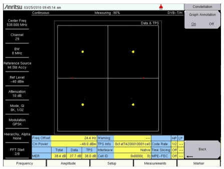
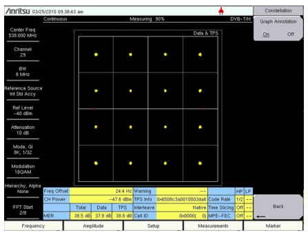
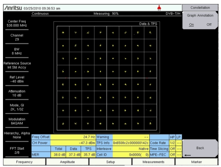
When Graph Annotation is turned Off, the constellation graphs are divided into 4 quadrants. When Graph Annotation is turned On, additional grid lines are displayed. The grid lines vary in value and spacing depending upon the hierarchy setting.