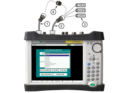
Various calibrations are available in the LMR Master. Press Shift-2 (Calibration) to open the calibration menu. Press Start Cal and follow the instruction on the screen. 1-Port calibration is the simplest and requires three connections during calibration. 2‑Port calibration requires four calibration connections and corrects for the transmit port match.
VNA calibration requires external precision OSL calibration components. 2-Port calibration also requires a through connector (Figure: Calibration).
Note
The Vector Network Analyzer Calibration menu is the same one that is used in the Vector Voltmeter menu (Option 15). Refer to section “Calibration Menus” in Chapter 6 of the Vector Network Analyzer Measurement Guide (refer to Measurement Guides in this publication for a listing of all measurement guides) for more information about the calibration menu. Note that some calibration parameters are shared between the Vector Network Analyzer and Vector Voltmeter mode, and that some parameters are different because they were optimized for the specific mode application.
Through Connection for 2 Port Calibration (Port 1 Connects to Port 2)
When performing a calibration, the correction coefficients are calculated for specific measurements (depending on the type of calibration chosen) and for instrument settings (frequency range, number of points, and power level). The term “calibration correction” refers to the correction coefficients that are applied to measurements as a result of your calibration.
When calibration correction is On, the correction is applied to all applicable measurements. For example, if a 1‑port calibration is performed, then only traces that measure reflection have a valid calibration. For those traces, the calibration information data in the Instrument Settings Summary (item 1 in Figure: Field Mode View VNA Display with GPS On) shows “CAL: ON (OK)”. Other traces that do not measure reflection display “CAL: --” to indicate that no valid calibration is available for those traces. The calibration correction can also be turned off manually under the Calibration menu by toggling the Cal Correction submenu key from On to Off. In that case, the display shows “CAL: OFF” for all traces that have valid correction data available.
Note that “CAL: OFF” means that a calibration correction has been created, but it is not currently being used. This is different from “CAL: --”, which means that no valid calibration correction is available for the current setting.
When you have Cal Correction on, you cannot increase the frequency range or the number of points. You can, however, reduce the frequency range or decrease the number of points without forcing the calibration to become invalid. When reducing the frequency range, the LMR Master uses the appropriate points within the new frequency range that have correction coefficients applied to them. In that case, you can observe that the number of points that are being used for calibration correction are automatically reduced.
If you reduce only the number of points, then the frequency range is not changed. The LMR Master finds a subset of the original points in the sweep that can be used. You can therefore notice that the instrument may not use the exact number of points that you have entered. It picks a specific number of points that allow the calibration correction to continue to be valid. If you use the rotary knob, you will more easily find the available number of points that can be set. For example, if you calibrated with 201 points, then you can observe that you can reduce the number of points to 101, 68, 51, 41, and so forth.
If you change the source power setting, the calibration status is changed to “CAL: ON (?P)”, which indicates that source power has changed since the instrument was calibrated (from Low to High, or from High to Low). In this case, the calibration may still be valid, but a new calibration is recommended.
Another status information display that you may see is “CAL: ON (?T)” which indicates that the instrument temperature has deviated by more than a set amount since the time that the calibration was conducted. The calibration is most likely still valid, but a new calibration is recommended. If you see “CAL: ON (X)” on the display, then this indicates that the instrument temperature has deviated (since the time the calibration was conducted) by an amount that has more than likely rendered the calibration invalid. When this occurs, a new calibration is highly recommended before further measurements are conducted.
Only one calibration is available at one time. Performing a new calibration overwrites any existing calibration. You can, however, store a measurement setup (with CAL), which also stores the calibration. You can therefore have multiple calibrations available (as long as the calibration settings and conditions continue to apply).
Existing Cal Info
The Cal Info submenu key is found in the Calibration main menu and lists the current calibration settings.
Note
If you update the firmware for an LMR Master, you will have to recalibrate the instrument. Before loading new firmware, make note of the calibrations set on this instrument and make sure that the required supplies to re-establish those calibrations are available.