• Option 31, GPS is required for Interference Mapping
• Option 25, Interference Analysis
• Directional antenna and compass
1. Capture a map using Anritsu easyMap Tools.
Anritsu easyMap Tools allows you to capture maps of any location and create Anritsu Map Files. These Geo-enabled maps are viewed on the Anritsu instrument during interference mapping. There are two Anritsu Map Files formats: (.map and .azm) used for Interference Mapping.
• .azm are map files allow Pan and Zoom on the instrument.
• .map are map files are in a legacy format compatible with older firmware.
The map should extend beyond the estimated location of bearing readings and have the general location of the interferer centered in the map.
2. Move the map file to the Anritsu instrument.
Copy the map file to a USB memory stick and then insert the memory stick into the Anritsu instrument’s USB Type A port. Anritsu recommends copying the map file to the instrument’s internal memory. Refer to Anritsu instrument User Guide for additional information.
3. Set the Anritsu instrument to IA Mapping and configure the instrument.
A. Connect a directional antenna in the frequency range of interest to the Anritsu instrument’s RF In connector.
B. Open up the Interference Analyzer by pressing the Menu key and selecting the Interference Analyzer icon or press Shift then Mode (9), highlight Interference Analysis and press Enter.
C. Press the Measurements main menu key then press the Interference Mapping submenu key twice to display the Interference Mapping menu.
D. Turn on GPS.
a. Press Shift then System (8).
b. Press the GPS submenu key.
c. Connect a GPS antenna to the SMA connector.
d. Set the GPS voltage to match the antenna you are using, then press the GPS On/Off submenu key to select On.
e. Press GPS Info and verify that the information from three or more satellites is captured. Press Esc to close the info box.
It may take several minutes for the GPS receiver to lock. When it does the GPS icon at the top of the screen is solid green and location information is displayed. Refer to the User Guide for your instrument for additional information about GPS.
E. Set the frequency (Freq > Center Freq) for mapping.
4a. Load (Recall) the map file.
The instrument allows you to recall a .map or .azm file (created with Anritsu easyMap Tools). With a valid GPS signal, the current location will be displayed on the map or an arrow will show the direction of the current location if it is outside the map coverage area.
A. Press the IA Mapping main menu key at the bottom of the screen.
B. Press the Save/Recall Points/Map submenu key.
C. Press Recall a Map and select the File Type (AZM or MAP).
D. Use the arrow keys to scroll down to the desired map and press Enter to select.
E. The new map file will be displayed and the current location (if within the GPS boundaries of the displayed map) is shown as a plus sign.
F. AZM maps allow zoom and pan. Refer to Pan & Zoom Menu for additional information.
G. If the current location is outside the map boundaries, a black arrow will indicate the direction of the current location in relation to the displayed map.
Note
You can load a different map at any time. Captured bearings will be displayed on or off the map in the same manner as described above.
or
4b. Recall the Default Grid option.
With a valid GPS signal, the instrument is able to make interference mapping measurements even when an Anritsu easyMap Tools file of the current location is not available. Location, signal strength, and bearing information can be saved in a (.kml) file. Details of each time the Save Current Bearing Location & Direction submenu key was pressed can be viewed at a later time on the instrument or in Google Earth. Refer to Mapping Save/Recall Menu for additional information on recalling saved maps and .kml data.
Note
When using the default grid, the coverage area for Interference Mapping is fixed at 10 miles by 10 miles. The location will be centered on the default map. For example, if you go to the east by 15 miles, then there will be an arrow indicating where you went off the map. You can at this point load a new Default Grid and the current location will be at the center of the display.
A. Press the IA Mapping main menu key at the bottom of the screen.
B. Press the Save/Recall Points/Map submenu key.
C. Press the Recall Default Grid submenu key.
Locating an Interfering Signal with the Default Grid
5. Map the interfering signal.
Once you have the GPS signal, directional antenna, and the GeoEmbedded map or the default grid map loaded on the instrument, you can start locating interfering signals. The plus sign shows the current location on the screen.
A. Press the Measurements main menu key then the Interference Mapping submenu key.
B. Use the directional antenna to locate the bearing of the strongest signal. Rotate the knob on the Anritsu instrument until the red line on the display is aligned with the direction of the interfering signal. Under the Bearing Lines submenu, press the Save Current Bearing Location & Direction key to save the current location and direction.
Note
A compass may be helpful to determine the bearing of the strongest Antenna signal. Use the rotary knob on the instrument to match the direction (shown at the bottom of the display) of the vector on the screen to the compass bearing (or a landmark) of the strongest signal before pressing the Save Current Bearing Location & Direction submenu key.
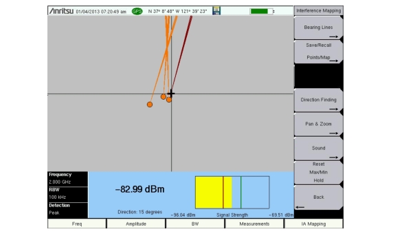
C. Move to the next location and repeat step 5B. You now have two lines on the screen and an idea of where the interfering signal is located. Pan & Zoom as needed (if using an AZM map). An example of interference mapping where approximate location of the interferer is determined is shown in Figure: Interference Mapping Overview.
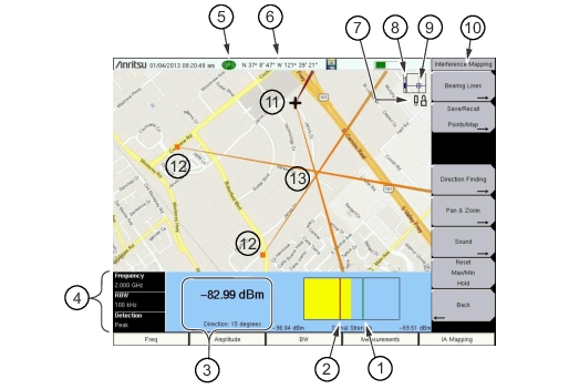
Interference Mapping Overview
1
Maximum signal level.
2
Minimum signal level.
3
Current readings.
• Power level: Displays the power level at the Anritsu instrument’s receiver.
• Direction: Bearing of the active vector (red). Adjust with the rotary knob on the Anritsu instrument.