Interference Mapping requires GPS Option 31 or the MA2700A which contains a GPS module.
Interference Mapping assists in quickly identifying the location of an interfering signal using a directional antenna and a GeoEmbedded map created using Anritsu easyMap Tools software.
The easyMap Tools program creates single panel maps (.map) for use with Anritsu instruments. easyMap Tools also creates pan and zoom maps (.azm) compatible with supported Anritsu instruments. The software imports maps from OpenStreetMap and Google Maps and creates files with or without GPS information. Anritsu easyMap Tools is available from the Anritsu website (www.anritsu.com).
Note
For a list of supported instruments, refer to easyMap Tools Help.
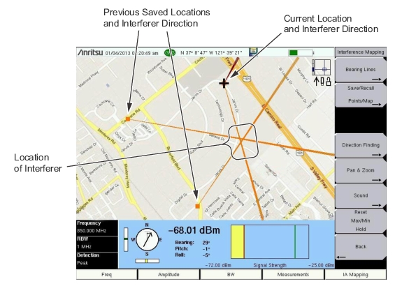
With a valid GPS signal, the instrument will identify the current location on the displayed map with a plus sign. Saved locations are displayed with an orange square. The direction of the interfering signal can be determined and recorded. With two or more lines, you can see where the lines intersect and estimate the location of the interferer.
Interference Mapping with the MA2700A Handheld Direction Finding System
Overview
1. Capture a map using Anritsu easyMap Tools. Both non-zoomable (.map) and zoomable (.azm) map file formats are appropriate.
2. Copy the map file to a USB memory stick and then insert the memory stick into the Anritsu instrument’s USB Type A port. Anritsu recommends copying the map file to the instrument’s internal memory.
3. Set the Anritsu instrument to IA mapping and configure the instrument.
4. Load (Recall) the map file.
5. Map the interfering signal.
6. Save the mapping information.
7. View (recall) saved mapping information.
• Saved Maps and KML points can be viewed on the Anritsu instrument. The user may want to clear any existing points before recalling the map. Refer to Bearing Lines Menu.
• Saved Maps, KML points, Tab Delimited Points, and JPG files can be transferred and viewed on a PC. Refer to Mapping Save/Recall Menu.
The actual mapping process varies based on the direction finding equipment. The process is described in the following sections:
Measurement updates (including bearing and signal strength) are controlled by settings of the Anritsu instrument’s Sweep menu (Shift+3) settings and Triggering Source (Sweep > Triggering > Trigger Source) settings.
The preset parameters (Sweep = Continuous and Trigger Source = Free Run) allow for continuous measurement updates.
If the instrument display is not updating as expected, confirm these settings. Additional information is available in Sweep Menu and Trigger Source Menu.