The Anritsu Instrument must have Interference Analysis (Option 25) and SPA module V6.00 or higher firmware to use Anritsu easyMap Tools.
Anritsu instrument requirements:
• Option 25, Interference Analysis.
• Anritsu’s MA2700A Handheld Direction Finding System (Includes GPS and electronic compass).
1. Capture a map using Anritsu easyMap Tools.
Anritsu easyMap Tools allows you to capture maps of any location and create Anritsu Map Files. These Geo-enabled maps are viewed on the Anritsu instrument during interference mapping. There are two Anritsu Map Files formats: (.map and .azm) used for Interference Mapping.
• .azm map files allow Pan and Zoom on the instrument.
• .map map files are in a legacy format compatible with older firmware.
The coverage map should extend beyond the estimated location of bearing readings and have the general location of the interferer centered in the map.
2. Move the map file to the Anritsu instrument.
Copy the map file to a USB memory stick and then insert the memory stick into the Anritsu instrument’s USB Type A port. Anritsu recommends copying the map file to the instrument’s internal memory. Refer to Anritsu instrument User Guide for additional information.
3. Set the Anritsu instrument to IA Mapping and configure the instrument.
A. Connect the RF cable and USB cable from the MA2700A Handheld Interference Hunter (HIH) to the instrument.
C. Connect a directional antenna in the frequency range of interest to the MA2700A.
D. Setup the instrument for interference mapping mode by pressing the Menu key and selecting the Interference Analyzer icon or press Shift then Mode (9), highlight Interference Analysis and press Enter. Under the Measurements main menu, select Interference Mapping.
E. The instrument will detect the connected MA2700A and display the message MA2700A detected -- Device is ready to use. After GPS lock, the instrument will use GPS data from the MA2700A.
Note
Once detected, the MA2700A can be used to capture bearing and/or GPS data while in other Interference mode measurements and even other supported instrument measurement modes, including Spectrum Analyzer mode.
F. To manually select the MA2700A, confirm the MA2700A USB connection, then:
a. Press the Measurements main menu key then press the Interference Mapping submenu key twice to display the Interference Mapping menu.
b. Press the Direction Finding submenu button.
c. Press the Direction Finding Antenna Selection submenu button and select MA2700 Handheld.
It may take several minutes for the MA2700A GPS receiver to lock. When it does the GPS icon at the top of the screen is solid green and location information is displayed. Refer to the User Guide for your instrument for additional information about GPS.
G. Set the frequency (Freq > Center Freq) for mapping.
4a. Load (Recall) the map file.
The instrument allows you to recall a .map or .azm file (created with Anritsu easyMap Tools). With a valid GPS signal the current location will be displayed on the map or an arrow will show the direction of the current location if it is outside the map coverage area.
A. Press the IA Mapping main menu key at the bottom of the screen.
B. Press the Save/Recall Points/Map submenu key.
C. Press Recall a Map and select the File Type (AZM or MAP).
D. Use the arrow keys to scroll down to the desired map and press Enter to select.
E. The new map file will be displayed and the current location (if within the GPS boundaries of the displayed map) is shown as a plus sign.
F. AZM maps allow zoom and pan, refer to Pan & Zoom Menu for additional information.
G. If the current location is outside the map boundaries, a black arrow will indicate the direction of the current location in relation to the displayed map.
or
4b. Recall the Default Grid option.
With a valid GPS signal, the instrument is able to make interference mapping measurements even when an Anritsu easyMap Tools file of the current location is not available. Location, signal strength, and bearing information can be saved in a (.kml) file. Details of each time the MA2700A trigger is pressed can be viewed at a later time on the instrument or in Google Earth. Refer to Mapping Save/Recall Menu for additional information on recalling saved maps and .kml data.
Note
When using the default grid the coverage area for Interference Mapping is fixed at 10 miles by 10 miles. The location will be centered on the default map. For example, if you go to the east by 15 miles, then there will be an arrow indicating where you went off the map. You can at this point load a new Default Grid and the current location will be at the center of the display.
A. Press the IA Mapping main menu key at the bottom of the screen.
B. Press the Save/Recall Points/Map submenu key.
C. Press the Recall Default Grid submenu key.
Locating an Interfering Signal with the MA2700A and the Default Grid
5. Map the interfering signal with the MA2700A.
Once you have a GPS signal from the connected Handheld Interference Hunter with a directional antenna, and the GeoEmbedded map or the default grid map loaded on an instrument, you can start locating interfering signals. The plus sign shows the current location on the screen.
A. Press the Measurements main menu key then the Interference Mapping submenu key.
B. Use the MA2700A HIH with a directional antenna to locate the bearing of the strongest signal. When the HIH is aligned with the direction of the interfering signal briefly pull and release the trigger on the HIH to record the current location and bearing line of the interferer.
Pulling the MA2700A trigger will prompt the Anritsu analyzer to beep. Releasing the pulled trigger has two functions:
• Release the trigger after the initial beep (< 1 second) to capture location and signal data. This has the same function as pressing the Save Current Bearing Location & Direction submenu key (refer to Bearing Lines Menu).
• Release the trigger after the second beep (~ 2 seconds) to toggle the preamp in the MA2700A and the Anritsu analyzer On or Off.
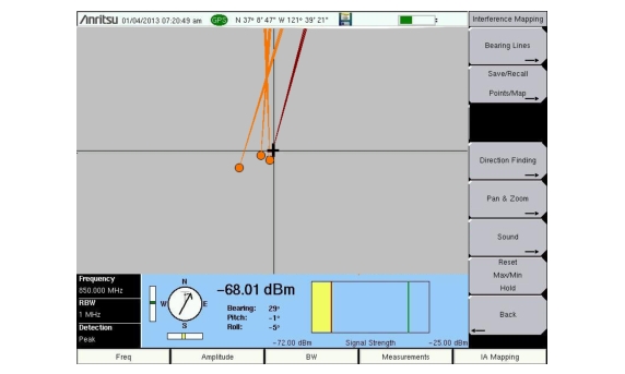
The compass acquires the bearing line data for the MA2700A Handheld Interference Hunter. The compass will display a light gray T or M; T for true North, M for magnetic North. The pitch and roll indicators will display how level and plumb the MA2700A is while searching for interference signals. The compass bearing is most accurate when the MA2700A is level. To the right of the compass and pitch and roll indicators are the numerical values for Bearing, Pitch, and Roll.
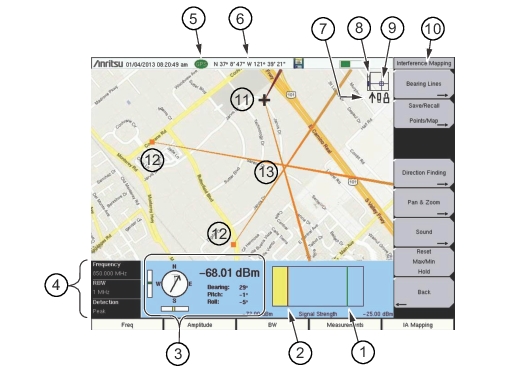
C. Move to the next location and repeat step 5B. You now have two lines on the screen and an idea of where the interfering signal is located. Pan & Zoom as needed (if using an AZM map). An example of interference mapping with the MA2700A where the approximate location of the interferer is determined is shown in Figure: Interference Mapping Overview (1 of 2).
Interference Mapping Overview (1 of 2)
1
Maximum signal level.
2
Minimum signal level.
3
Current readings from the MA2700A.
• Compass: Before GPS lock, the compass displays a light gray M indicating magnetic north (no declination adjustment). With GPS lock, a declination adjustment is automatically applied based on location and the compass changes to display a light gray T indicating true north. The Arrow indicates the direction the MA2700A is pointing.
• Power level: Displays the power level at the Anritsu instrument’s receiver.
• Bearing: Direction the MA2700A is pointing (shown in red).
• Pitch (vertical level): Indicates the front-to-back orientation.
• Roll (horizontal level): Indicates the side-to-side orientation.
Zoom level indication (when using .azm maps). Top is maximum zoomed in position. Bottom is maximum zoomed out position. Refer to Pan & Zoom Menu.
9
Current tile location in base map (when using .azm maps). Move the current tile location around the base map using the arrow keys on the Anritsu analyzer.
Note: Panning is not functional when the instrument displayed map is at the maximum zoomed out position.